Leak check for fuel vapor purge system
a technology of leak detection and purge system, which is applied in the direction of fluid tightness measurement, combustion air/fuel air treatment, instruments, etc., can solve the problems of fuel vapor purge system variable new problems, error in leak detection, and rapid change of fuel tank pressure, so as to reduce power consumption
- Summary
- Abstract
- Description
- Claims
- Application Information
AI Technical Summary
Benefits of technology
Problems solved by technology
Method used
Image
Examples
first embodiment
[0048](First Embodiment)
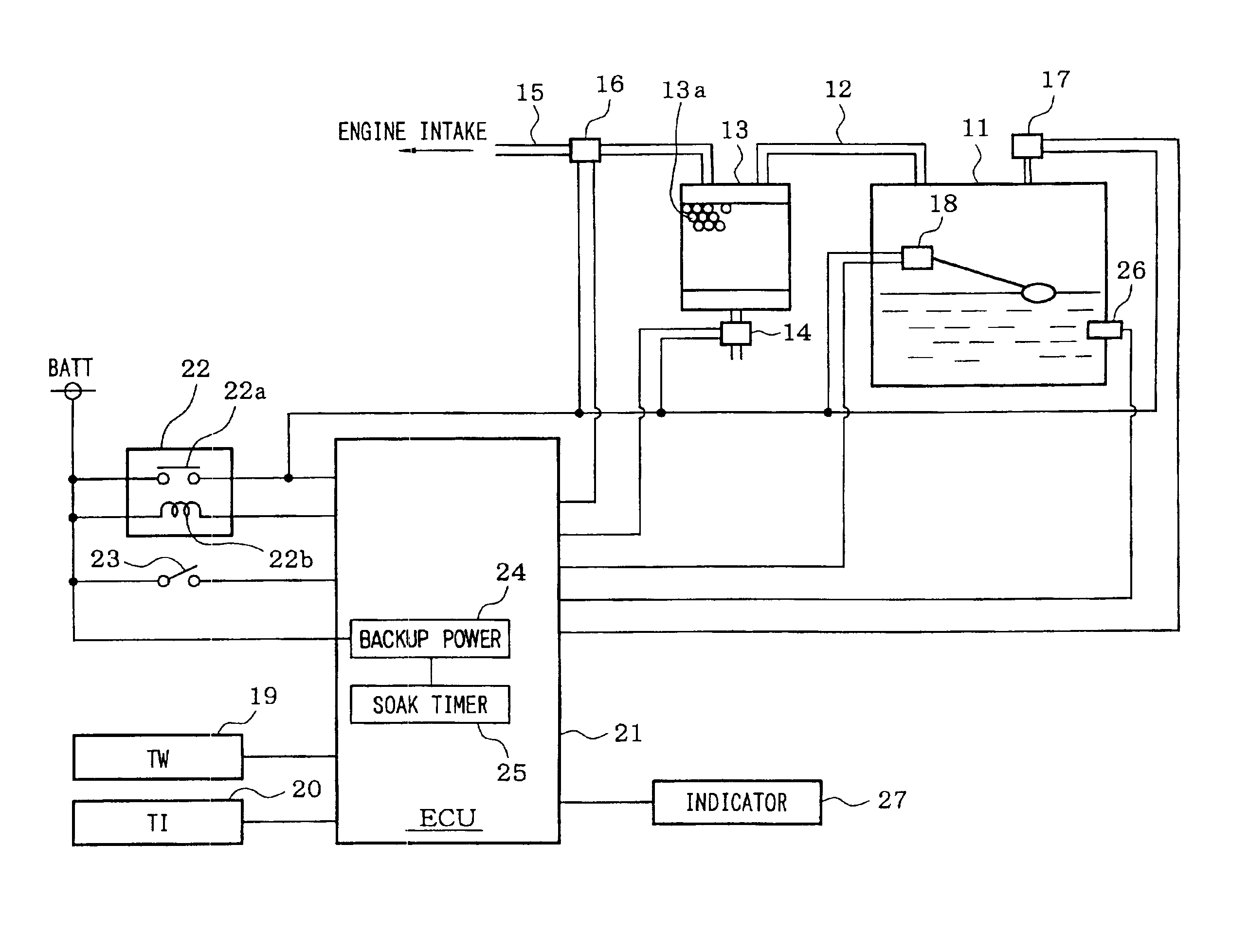
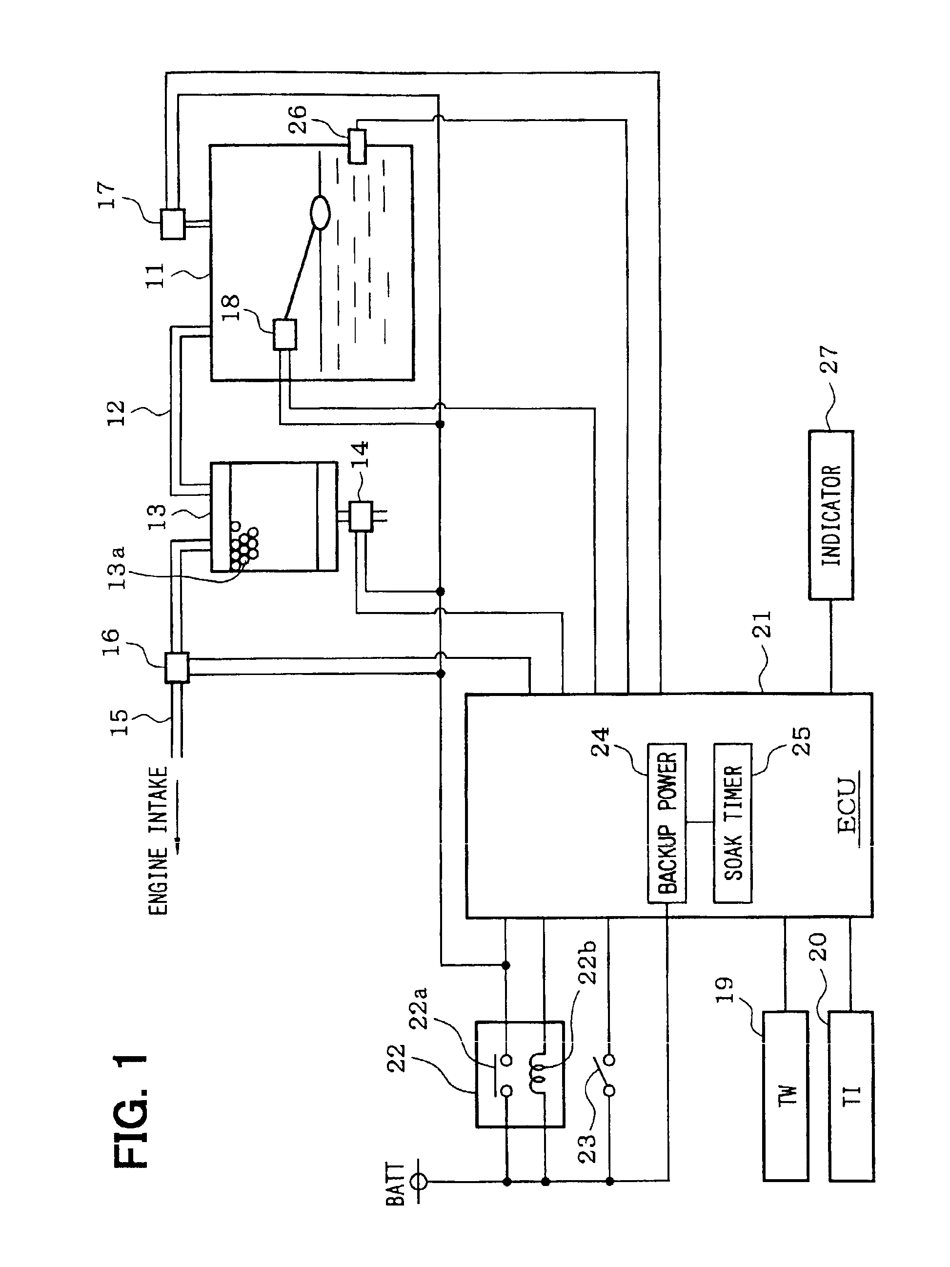
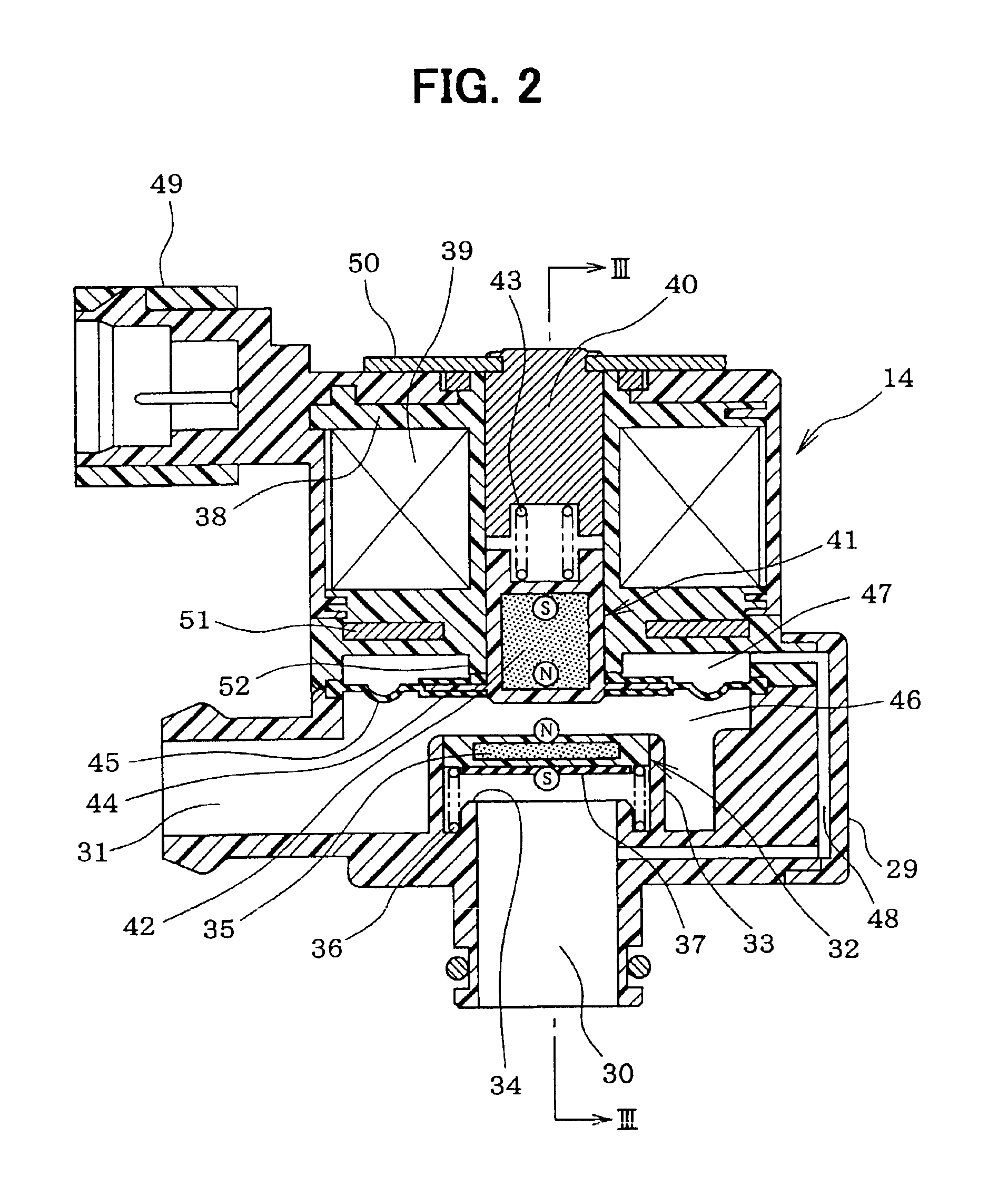
[0049]An explanation will be given of a first embodiment of the invention in reference to FIG. 1 through FIG. 7 as follows. First, an explanation will be given of a constitution of a fuel vapor purge system in reference to FIG. 1. A fuel tank 11 is molded by resin. The fuel tank 11 is connected with a canister 13 via a fuel vapor path 12. An adsorber 13a of active carbon or the like for adsorbing the fuel vapor is contained in the canister 13. Further, an atmosphere communicating path of a bottom face portion of the canister 13 is attached with a canister valve 14 (CCV) of a power saving type, mentioned later.
[0050]Meanwhile, between the canister 13 and an engine intake system, there is provided a purge path 15 for purging (discharging) fuel vapor adsorbed to the adsorber in the canister 13 to the engine intake system and a purge valve 16 for controlling a purge flow rate is provided at a middle of the purge path 15. The purge valve 16 is constituted by a nor...
second embodiment
[0090](Second Embodiment)
[0091]Next, an explanation will be given of a second embodiment of the invention in reference to FIG. 8 to FIG. 12. Elements the same as or similar to those in the first embodiment are attached with the same notations and an explanation thereof will not be repeated. According to the second embodiment, by executing a leak check routine shown in FIG. 8 and FIG. 9, during leak check after stopping the engine (after making IG switch 23 OFF) the pressure Pt is restricted by a predetermined positive pressure side restricted value PU and predetermined negative pressure side restricted value −PL and when the pressure Pt is rapidly changed (when deformation of fuel tank is brought about) in leak check, leak check is cancelled and the positive side restricted value PU or the negative pressure restricted value −PL is corrected in a direction of approaching the atmospheric pressure.
[0092]At step 306, it is determined whether the pressure Pt is higher than the predetermi...
third embodiment
[0114](Third Embodiment)
[0115]An explanation will be given of a third embodiment in reference to FIG. 14 through FIG. 16 as follows. A fuel vapor purge system according to the third embodiment is provided with components the same as those of the first embodiment. Leak check processings of the third embodiment differ from those of the first embodiment. According to the third embodiment, there is added a processing of temporary opening the canister valve 14 after finishing to check the leak. In the following explanation, elements the same as or similar to those of the first embodiment are added with the same notations and an explanation thereof will not be repeated.
[0116]Meanwhile, according to a conventional general fuel vapor purge system, there is used an electromagnetic valve of a normally open type for the canister valve in order to communicate the canister to the atmosphere in stopping to operate the engine and therefore, even after stopping to operate the engine, until finishin...
PUM
 Abstract
Description
Claims
Application Information
 - R&D
- Intellectual Property
- Life Sciences
- Materials
- Tech Scout
- Unparalleled Data Quality
- Higher Quality Content
- 60% Fewer Hallucinations
Browse by: Latest US Patents, China's latest patents, Technical Efficacy Thesaurus, Application Domain, Technology Topic, Popular Technical Reports.
© 2025 PatSnap. All rights reserved.Legal|Privacy policy|Modern Slavery Act Transparency Statement|Sitemap|About US| Contact US: help@patsnap.com


