Rotary steerable drilling tool and associated method of use

a rotary steerable and drilling tool technology, applied in the direction of drilling pipes, drilling rods, directional drilling, etc., can solve the problem of not being able to use in association with rotating drill strings

Inactive Publication Date: 2005-05-17
NAT OILWELL VARCO LP
View PDF26 Cites 30 Cited by
  • Summary
  • Abstract
  • Description
  • Claims
  • Application Information

AI Technical Summary

Benefits of technology

[0009]Skillful alternating of the two above drilling positions will yield a bo

Problems solved by technology

The bent subs are angled, and thus cannot be u

Method used


Image

  • Rotary steerable drilling tool and associated method of use
  • Rotary steerable drilling tool and associated method of use
  • Rotary steerable drilling tool and associated method of use

Examples


Embodiment Construction

[0031]In this patent document, “comprising” is used in its inclusive sense and does not exclude other elements being present in the device. In addition, a reference to an element by the indefinite article “a” does not exclude the possibility that more than one of the elements is present. MWD means measurement-while-drilling. All seals and bearings described herein and shown in the drawings are conventional seals and bearings.

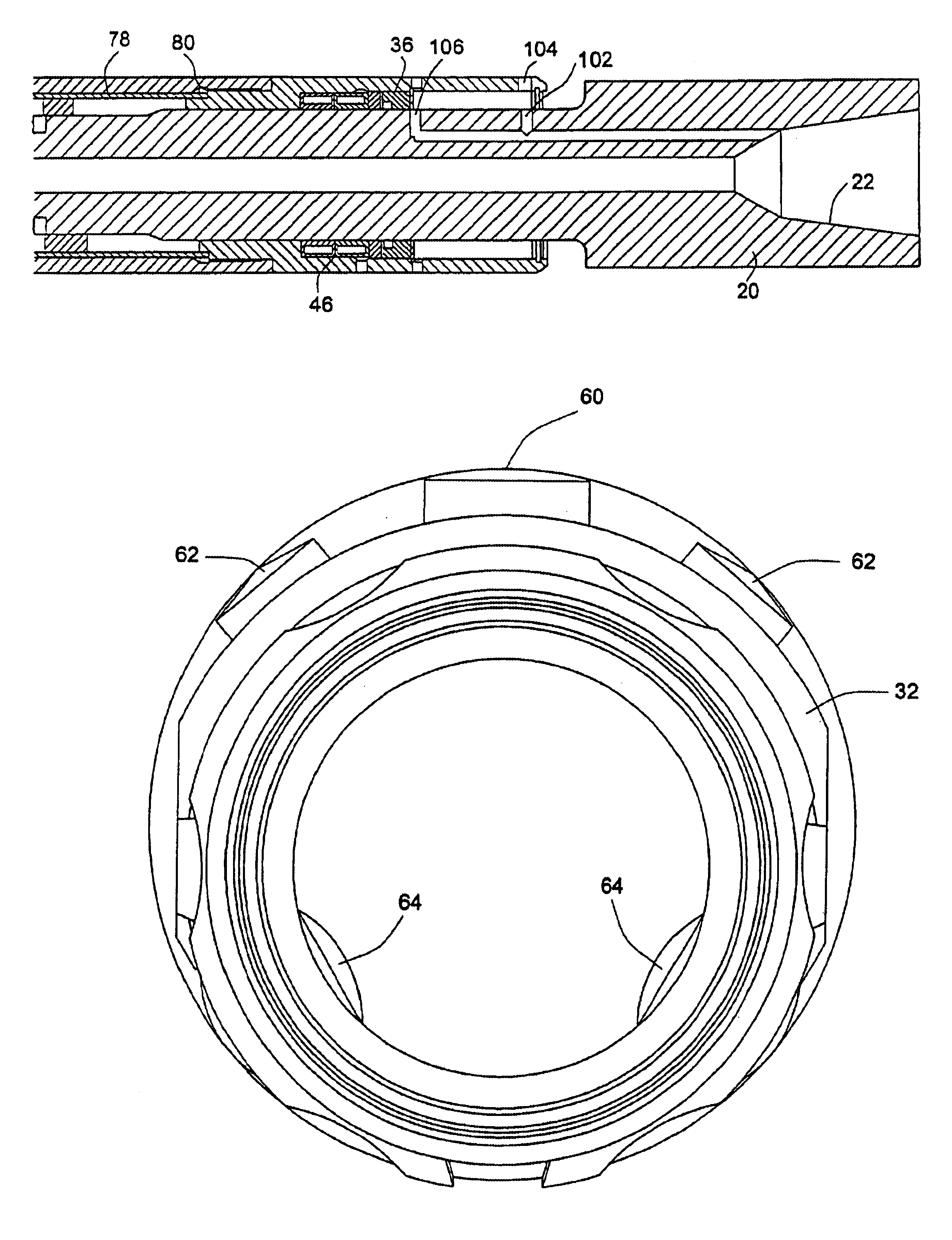
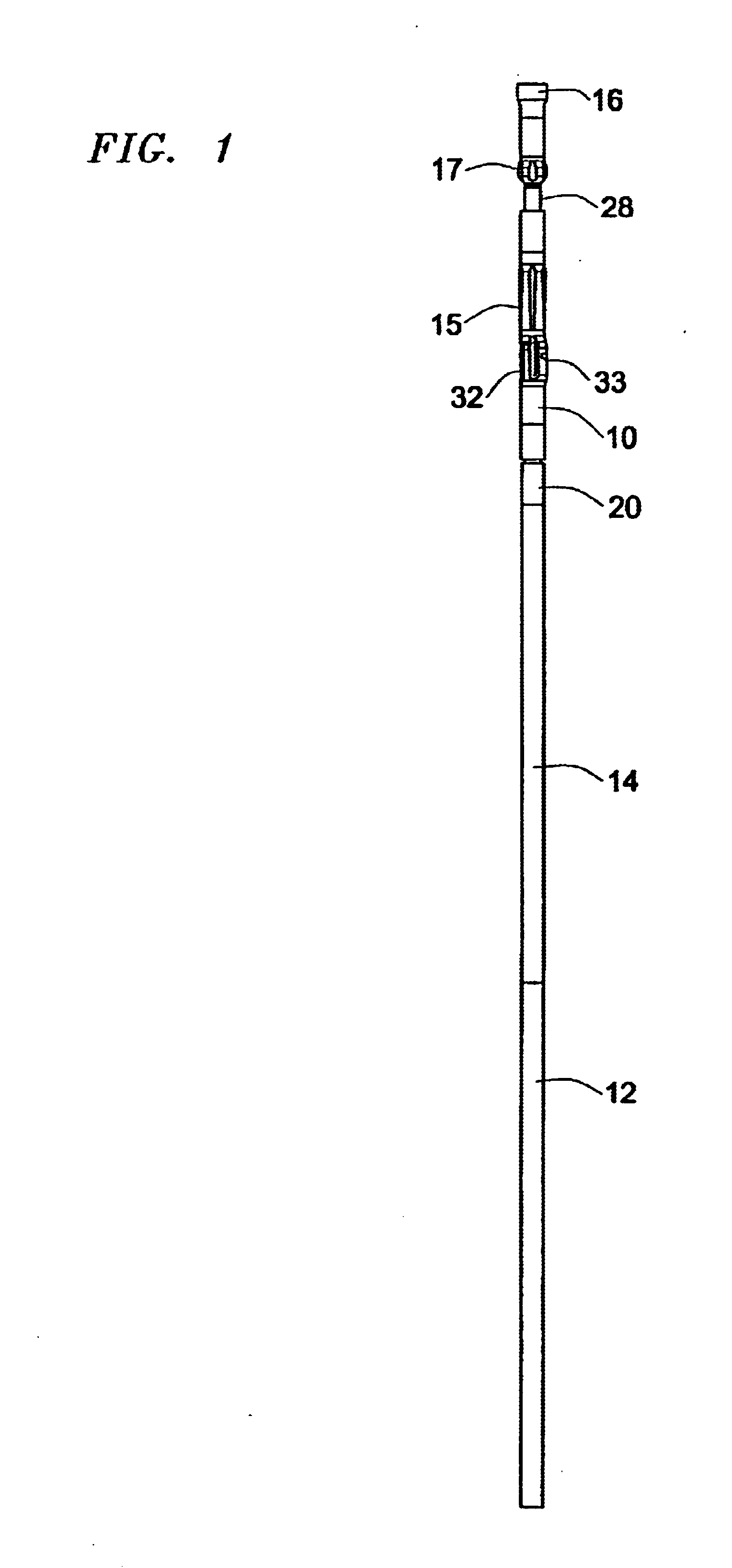
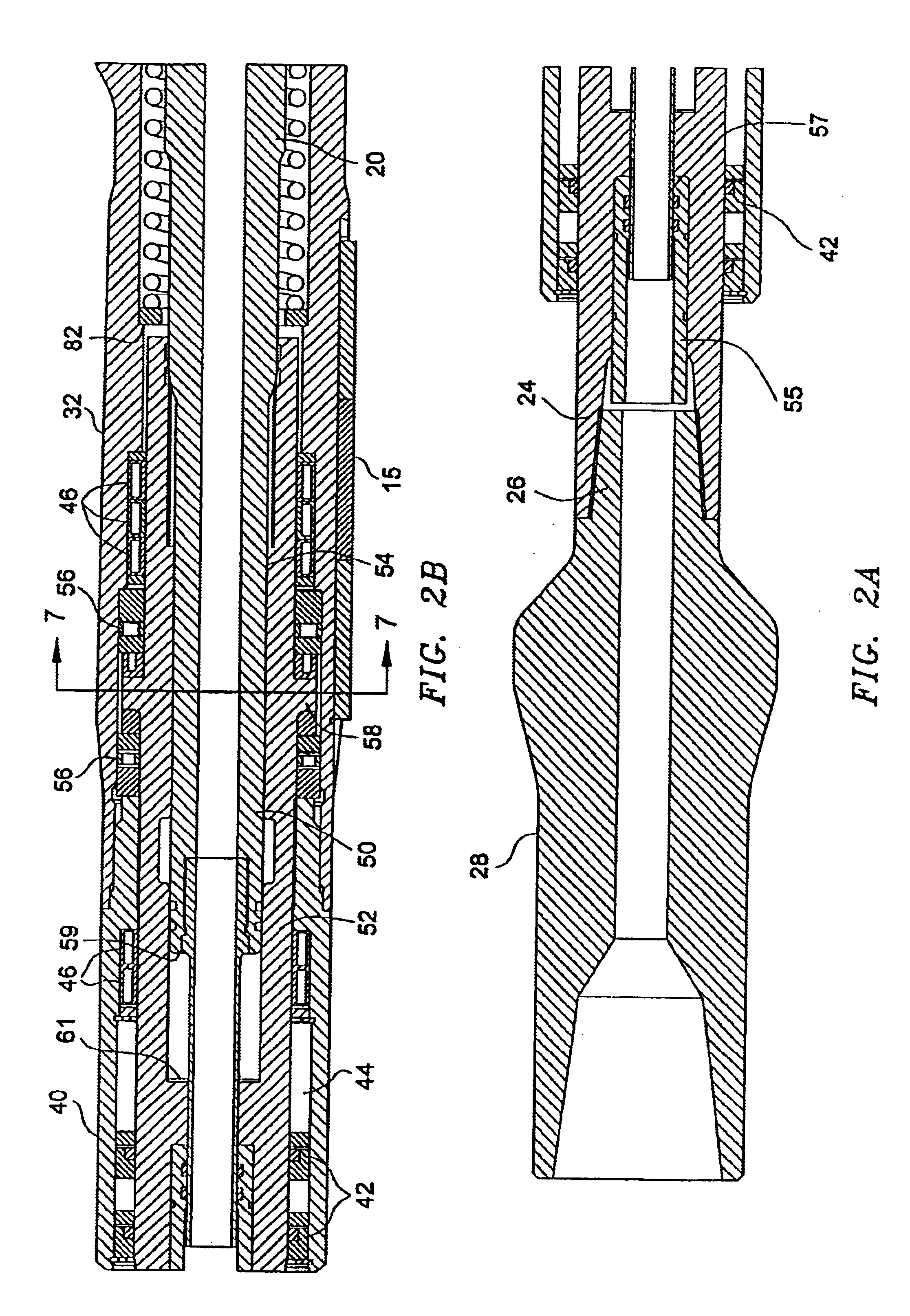
[0032]Referring to FIG. 1, which shows the overall assembly of a drill string according to the invention, a rotary steerable drilling tool 10 is shown located on a conventional drill string 12 between a conventional MWD tool 14 and a conventional drill bit 16. As shown more particularly in FIGS. 2A and 2D, rotary steerable drilling tool 10 includes a mandrel 20 having a conventional box connection 22 at an uphole end for connection into drill string 12 and a conventional box connection 24 at a downhole end for connection to a pin connection 26 of a drilling sub ...


PUM


Abstract

The device contemplated provides a method for positioning the drill bit in a drilling operation to achieve small changes in hole angle or azimuth as drilling proceeds. Two different positions are available to the operator. The first is a straight ahead position where the tool essentially becomes a packed hole stabilizer assembly. The second position tilts the bit across a rotating fulcrum to give a calculated offset at the bit-formation interface. The direction that the bit offset is applied in relation to current hole direction is controlled by positioning the orienting pistons prior to each drilling cycle, through the use of current measurement-while-drilling (MWD) technology. Components of the tool comprise a MWD housing, upper steering and drive mandrel, non-rotating position housing, lower drive mandrel splined with the upper mandrel, rotating fulcrum stabilizer and drill bit.

Description

RELATED APPLICATIONS[0001]This application is a divisional application based on prior application Ser. No. 09 / 907,480, filed on Jul. 17, 2001 now U.S. Pat. No. 6,595,303, which in turn is based upon prior U.S. provisional application Ser. No. 60 / 245,188 filed Nov. 3, 2000, which in turn is a U.S. provisional national application of prior Canadian application Serial No. 2,345,560, filed Apr. 27, 2001, the benefit of the filing date of which is hereby claimed under 35 U.S.C. §§119 and 120.FIELD OF THE INVENTION[0002]The invention relates to rotary drilling, and more particularly, to steered directional drilling with a rotary drilling tool.BACKGROUND OF THE INVENTION[0003]In the earth drilling art, it is well known to use downhole motors to rotate drill bits on the end of a non-rotating drill string. With the increasingly common use of directional drilling, where the well is drilled in an arc to produce a deliberately deviated well, bent subs have been developed for guiding the downhol...

Claims


Application Information

Patent Timeline
IPC IPC(8): E21B17/00E21B17/10E21B7/04E21B7/06E21B7/08
CPCE21B7/062E21B17/1014E21B7/067
Inventor NOE, PAULKUTINSKY, DAVID P.
Owner NAT OILWELL VARCO LP
Why Eureka
Try Eureka