

Sound radiating structure, acoustic room and sound scattering method
a sound radiating and acoustic room technology, applied in the field of improved sound radiating structure, acoustic room and sound scattering method, can solve the problems of large thickness of sound scattering members, affecting the sound scattering effect, and forming the projecting and depressed configuration, so as to reduce the degree of flexibility, increase the thickness of the structure, and good sound scattering
Inactive Publication Date: 2005-05-17
YAMAHA CORP
View PDF7 Cites 23 Cited by
- Summary
- Abstract
- Description
- Claims
- Application Information
AI Technical Summary
Benefits of technology
The present invention provides a sound radiating structure and a method for scattering sound using a resonant structure. The structure consists of multiple cavity-defining members that have inner cavities that resonate with sound waves, resulting in good sound scattering effects across wide frequency bands without increasing the thickness of the structure or decreasing its flexibility in design. The cavity-defining members are disposed perpendicular to each other, and they can be adjusted in length and have a flat outer surface. The invention also provides an acoustic room equipped with the sound radiating structure and a method for scattering sound using the resonant structure.
Problems solved by technology
However, in the first-mentioned conventional acoustic-obstacle obviating method characterized by attaching the sound scattering members of a mountain-shaped or semicircular section to the wall surfaces of the facilities, the sound scattering members, forming the projecting and depressed configurations, tend to have a considerably great thickness.
Thus, the interior space of the facilities would be greatly sacrificed if such thick sound scattering members are attached to the inner wall surfaces of the facilities.
Further, if the sound scattering members of the mountain-shaped or semicircular section are attached all over the inner wall surfaces of the facilities, the interior of the facilities would result in a uniform and monotonous outer appearance.
However, the projecting and depressed configuration can not be changed as desired because the sound scattering effects are afforded by such a configuration, with the result that the degree of flexibility or freedom in choosing the design is significantly limited.
In the second-mentioned conventional acoustic-obstacle obviating method characterized by the sound absorbing panels dispersedly attached to the inner wall surfaces, etc. of the facilities so as to provide alternating sound absorbing and sound reflecting regions on the wall surfaces, the sound absorbing effects of a number of the sound absorbing panels, although arranged dispersedly, would undesirably deteriorate the necessary acoustic liveness in the interior of the facilities.
In addition, this method is not satisfactory in that the sound scattering effects afforded thereby are not sufficient.
In addition, because the Shroeder-type sound scattering structure would absorb low-frequency sounds, it is not suitable for applications where great sound scattering effects are to be achieved in low sound pitch ranges.
Method used
View moreImage
Smart ImageViewing Examples

Examples
case 1-a
(Case 1-A)
[0080]Sound radiating structure where each of the pipes has a small wall thickness (see FIG. 12).
case 1-b
(Case 1-B)
[0081]Sound radiating structure where each of the pipes has a great wall thickness (see FIG. 13).
case 2-a
(Case 2-A)
[0082]Sound radiating structure where each of the pipes has the inward curved surface on the edge defining the side opening 13a (see FIG. 14).
Login to View More PUM
 Abstract
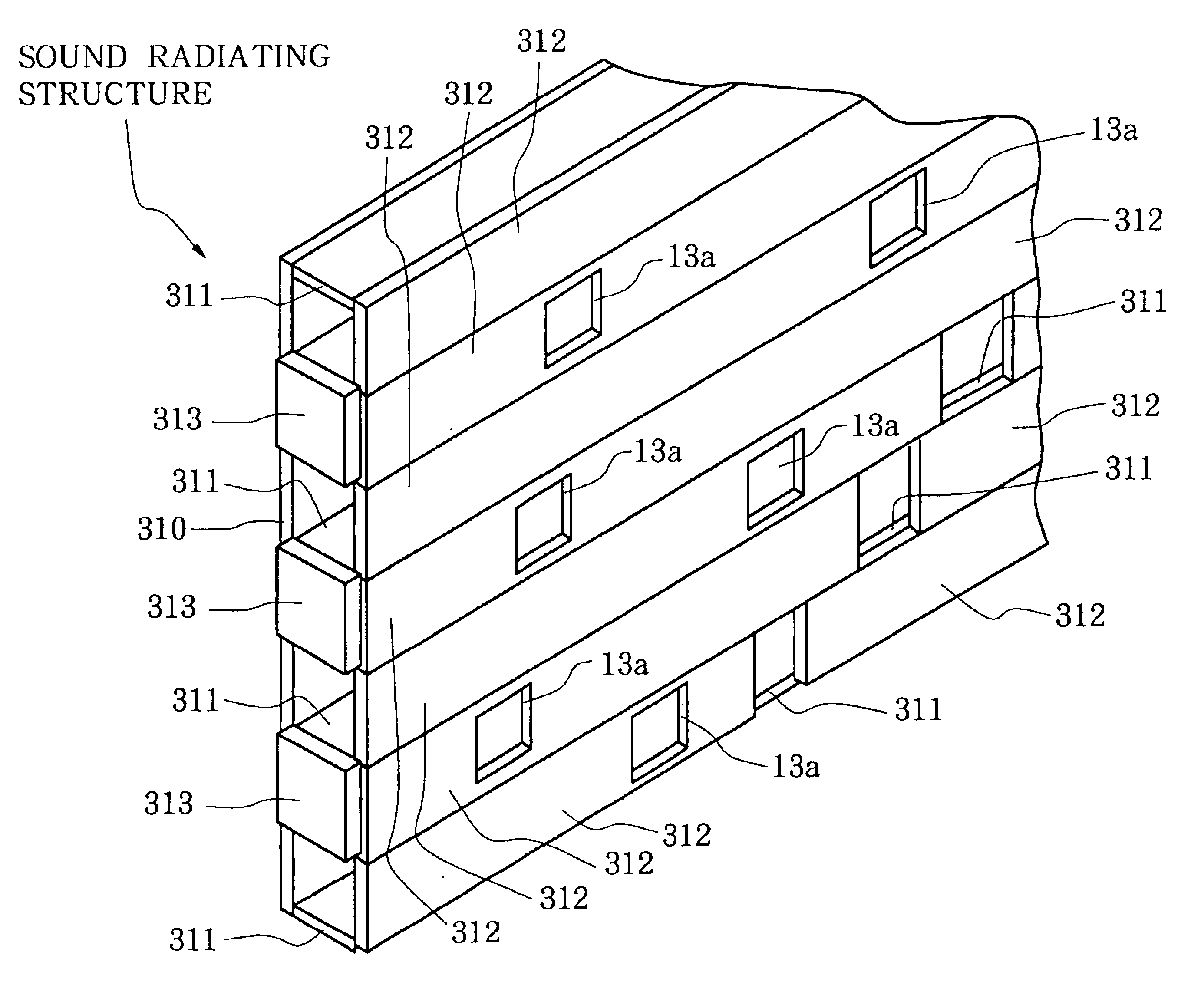
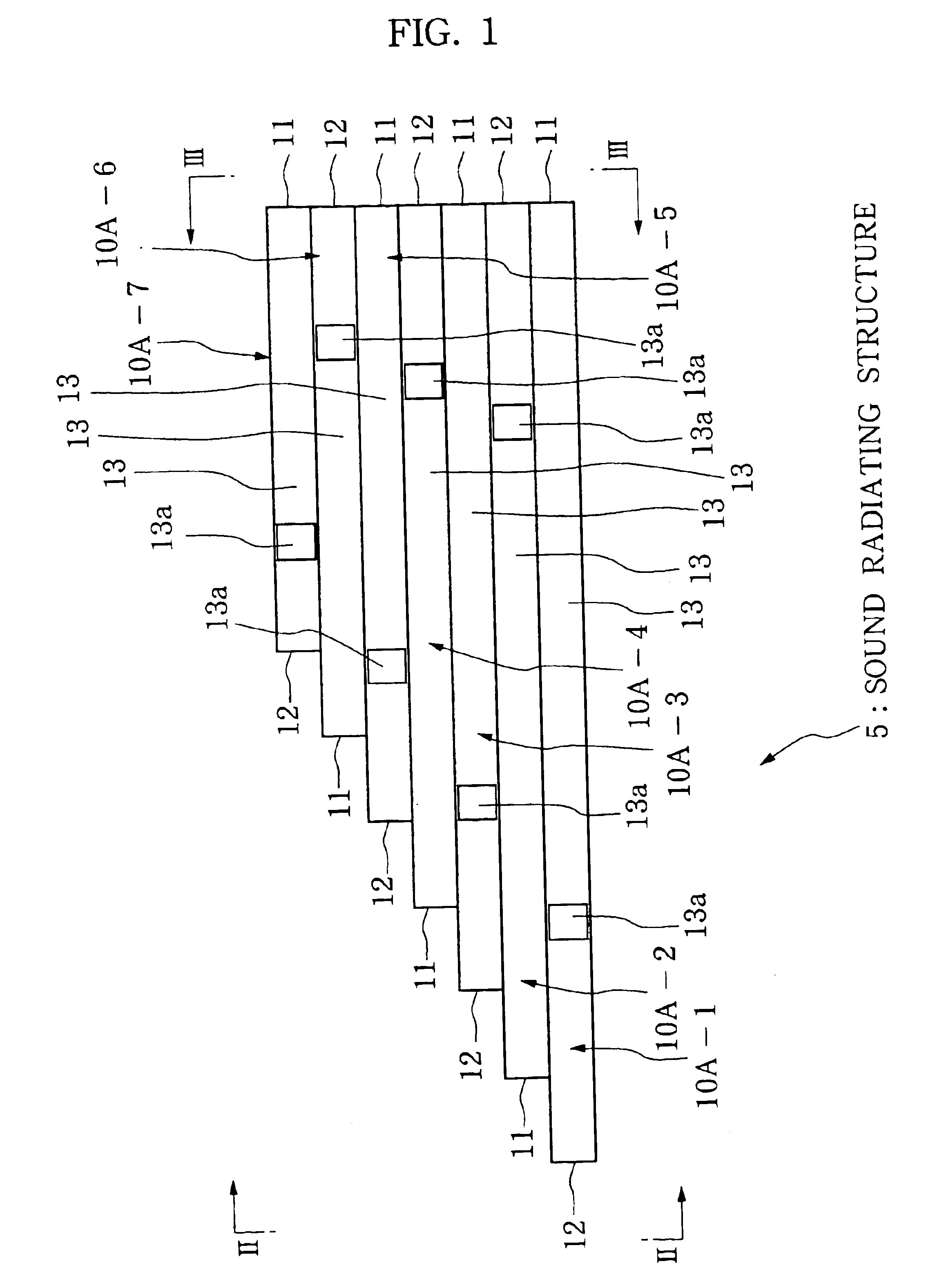
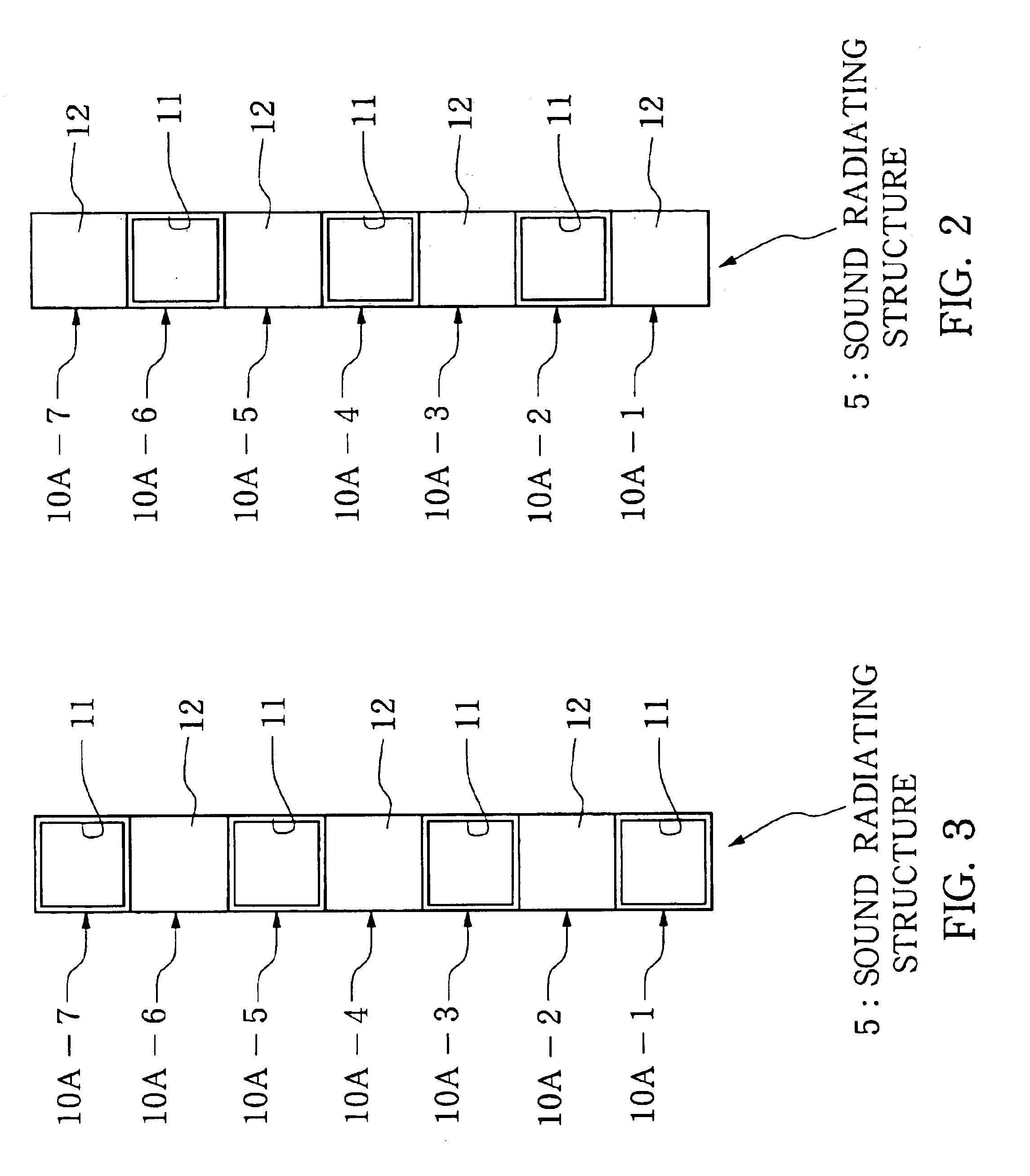
Sound radiating structure includes a plurality of pipes each defining an inner cavity along the length of the pipe. Each of the pipes has an end opening at one end and is closed at the other end with a closure. Each of the pipes also has a side opening in its one side portion. When a sound is input to the sound radiating structure, it re-radiates various sound waves through a number of the end and side openings together with reflected sound waves.
Description
BACKGROUND OF THE INVENTION[0001]The present invention relates to an improved sound radiating structure, acoustic room and sound scattering method.[0002]Heretofore, there have been proposed and known various methods for obviating sound or acoustic obstacles in concert halls, auditoriums or like facilities or acoustic rooms by scattering sounds. Among such known acoustic-obstacle obviating methods is one which is characterized in that sound scattering members, each having a mountain-shaped or semicircular section, are attached to wall surfaces of the hall or like facilities so that the projecting and depressed configurations formed by the sound scattering members can control directions of reflected sounds to thereby scatter the sounds. Another known example of the acoustic-obstacle obviating methods is characterized in that sound absorbing panels are attached dispersedly to the inner wall surfaces, ceiling surface, etc. of the facilities so that acoustic impedance can be varied to pr...
Claims
Login to View More Application Information
Patent Timeline
 Patent Type & AuthorityPatents(United States)
IPC IPC(8): G10K11/02G10K11/00E04B1/99G10K11/16
CPCG10K11/172
InventorTAKAHASHI, KENGOKOBAYASHI, TETSU
OwnerYAMAHA CORP