
Method for manufacturing micromechanical components

A micro-mechanical component and micro-mechanical technology, applied in the manufacture of micro-structure devices, electrical components, micro-structure technology, etc., can solve problems such as limiting the thickness of structural layers

Inactive Publication Date: 2009-01-21
VALTION TEKNILLINEN TUTKIMUSKESKUS
View PDF0 Cites 0 Cited by
  • Summary
  • Abstract
  • Description
  • Claims
  • Application Information

AI Technical Summary

Problems solved by technology

The thickness of this barrier layer, together with the thickness of LPCVD polysilicon, limits the thickness of the structural layer that can be obtained

Method used


Image

  • Method for manufacturing micromechanical components
  • Method for manufacturing micromechanical components
  • Method for manufacturing micromechanical components

Examples


Embodiment Construction

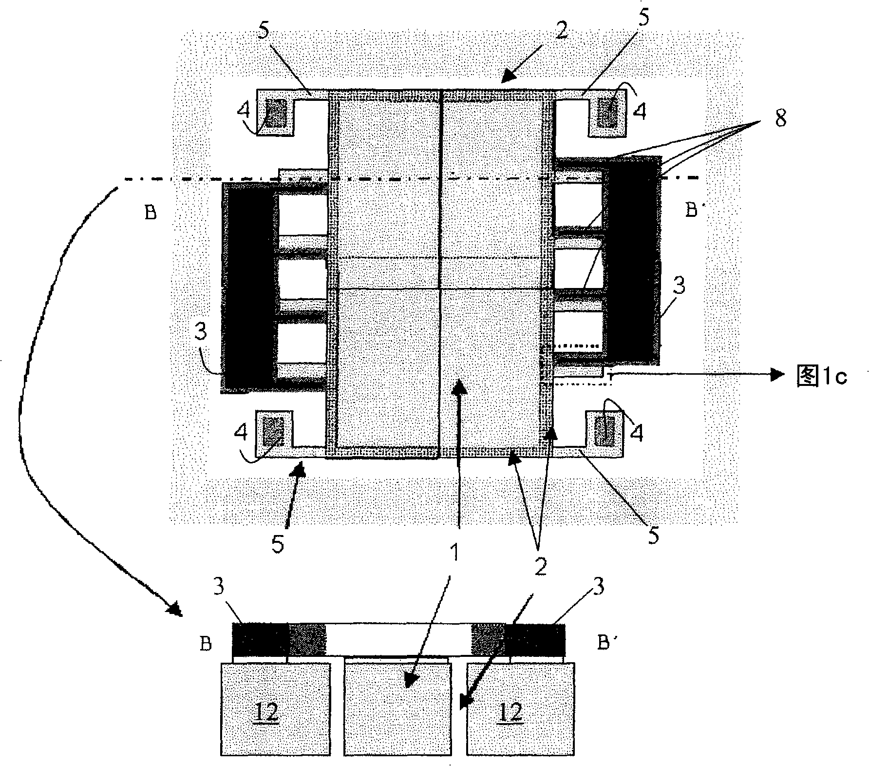
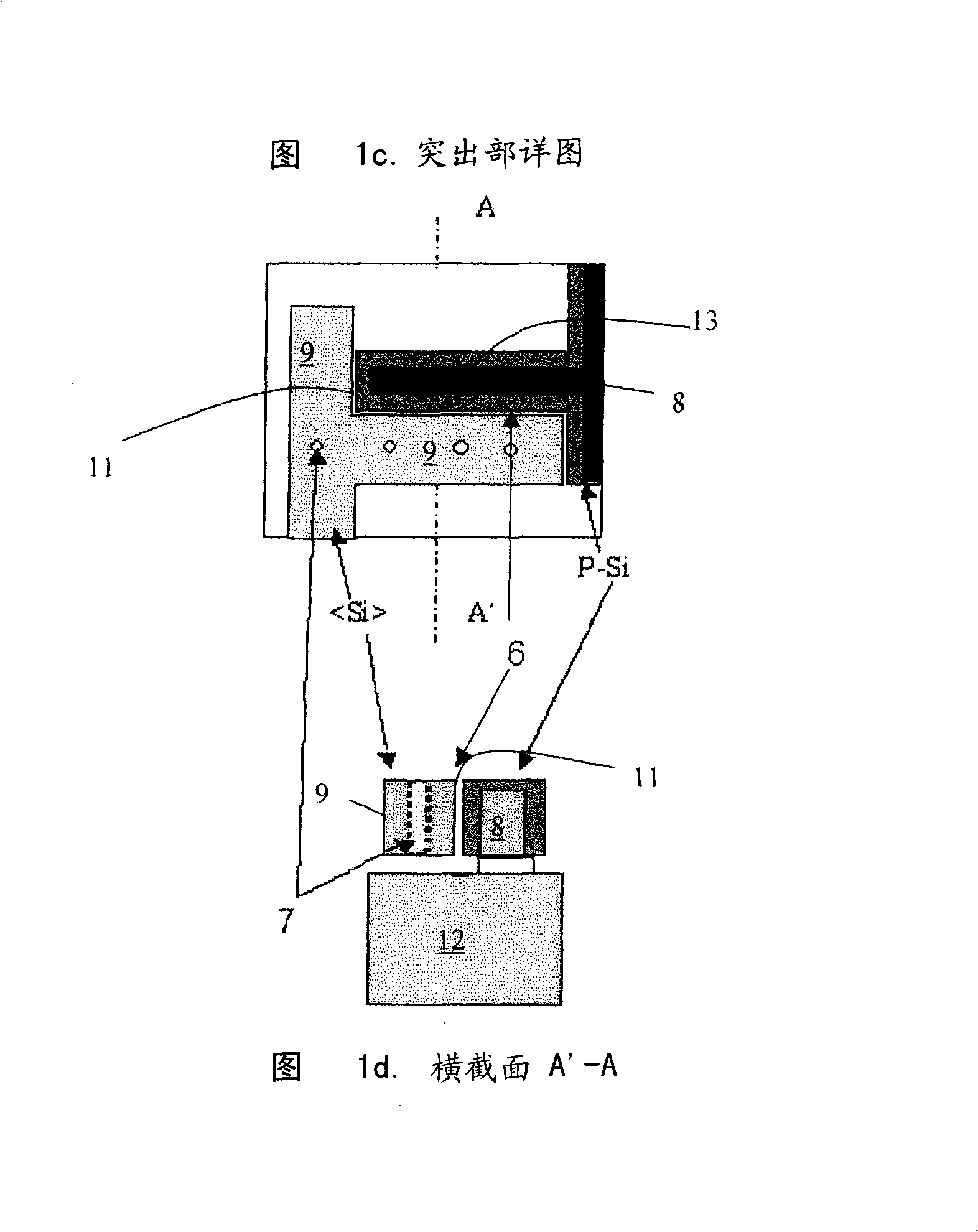
[0050] In FIG. 1 , a movable structure 1 made of monocrystalline silicon “floats” on four anchors 4 to which it is attached by means of suspension springs 5 ​​. A groove 2 is provided around the movable structure 1 , which groove ensures the mobility of said structure by separating the movable structure 1 from the substrate 12 . Detection holes 7 are also provided in single crystal silicon for release etching. In monocrystalline silicon, there are at least two protrusions 9, while a corresponding number of electrode protrusions 8 are arranged relative to them. Between the protrusion 9 and the electrode protrusion 8 of the monocrystalline silicon, a narrow gap 6 is etched, which is formed by a longitudinal groove 11 and a transverse groove 13 , and forms a gap in which the junction capacitance is formed by the protrusions 8 , 9 . The protrusions give the electrode structure a comb-like profile when viewed from above.

[0051] figure 2 The individual steps (steps 1-7) of a ma...


PUM

PropertyMeasurementUnit
widthaaaaaaaaaa
widthaaaaaaaaaa
thicknessaaaaaaaaaa

Abstract

The present invention relates to a method for manufacturing an acceleration sensor. In the method, thin SOI-wafer structures are used, in which grooves are etched, the walls of which are oxidized. A thick layer of electrode material, covering all other material, is grown on top of the structures, after which the surface is ground and polished chemo-mechanically, thin release holes are etched in the structure, structural patterns are formed, and finally etching using a hydrofluoric acid solution is performed to release the structures intended to move and to open a capacitive gap.

Description

technical field [0001] The present application relates to a method for obtaining narrow gaps in micromechanical components, in particular in micromechanical SOI-wafer structures, according to the preamble of claim 1 . [0002] The present invention also relates to the silicon micromechanical structure according to any one of claims 8-9, and the application of the silicon micromechanical structure according to any one of claims 20-21. Background technique [0003] According to prior art methods, silicon-micromechanical devices, such as acceleration sensors and other similar devices, are mainly manufactured by using SOI (silicon-on-insulator) wafer structures, on which grooves are etched, and the walls of the grooves are oxidized , and then the surface of the groove was made flat by fluorine-plasma etching. [0004] [W.-T.Hsu, J.R.Clark, and C.T.-C Nguyen, 'A sub-micron capacitivegap process for multiple-metal-electrode lateral micromechanical resonators by Hsu et al. Micron...

Claims


Application Information

Patent Timeline
Patent Type & Authority Applications(China)
IPC IPC(8): B81C1/00B81B
CPCB81C1/00611B81C2201/0125G01P15/125H03H3/0072
Inventor J·基哈马基H·卡特卢斯
Owner VALTION TEKNILLINEN TUTKIMUSKESKUS
Learn More