Height-adjustable support for elevating furniture

a technology of height adjustment and furniture, applied in the field of height, can solve the problems of affecting the stability of the device, the inability to adjust the range of the device, and the inability to stay in the desired position of the device, etc., and achieves the effects of convenient use, convenient construction, and convenient us

Inactive Publication Date: 2005-05-17
SOH SUNG KUK
View PDF26 Cites 44 Cited by
  • Summary
  • Abstract
  • Description
  • Claims
  • Application Information

AI Technical Summary

Benefits of technology

[0019]Such a support apparatus according to the invention is advantageous because it is compact in size, includes only a small number of parts, and is simple to construct, assemble and use. The apparatus according to the invention is reliable, durable, and inexpensive to manufacture, and is versatile in adjustability between multiple different heights. Optionally, the apparatus may be adapted to automatically maintain a desired orientation during use with a special / dedicated locking mechanism.
[0020]The support platform of the cradle may be shaped to fit virtually any shape or size furniture item, such as a bed leg, and the base can have a floor surface engaging portion of various shapes and sizes for assuring appropriate stability of the device in any application.

Problems solved by technology

Although the devices function appropriately for their intended uses, there are some drawbacks and disadvantages associated with the known devices.
For example, several of the known devices are limited in their range of adjustability, being adjustable only between a small number of positions.
Some of the previously known devices may become unstable during use, especially when set to a high level.
Some of the known devices have a tendency not to stay in a desired position unless an additional locking mechanism is provided for such purpose.
Some are relatively complicated and / or expensive to manufacture, some are relatively bulky, even when stored or shipped, etc.

Method used


Image

  • Height-adjustable support for elevating furniture
  • Height-adjustable support for elevating furniture
  • Height-adjustable support for elevating furniture

Examples


first embodiment

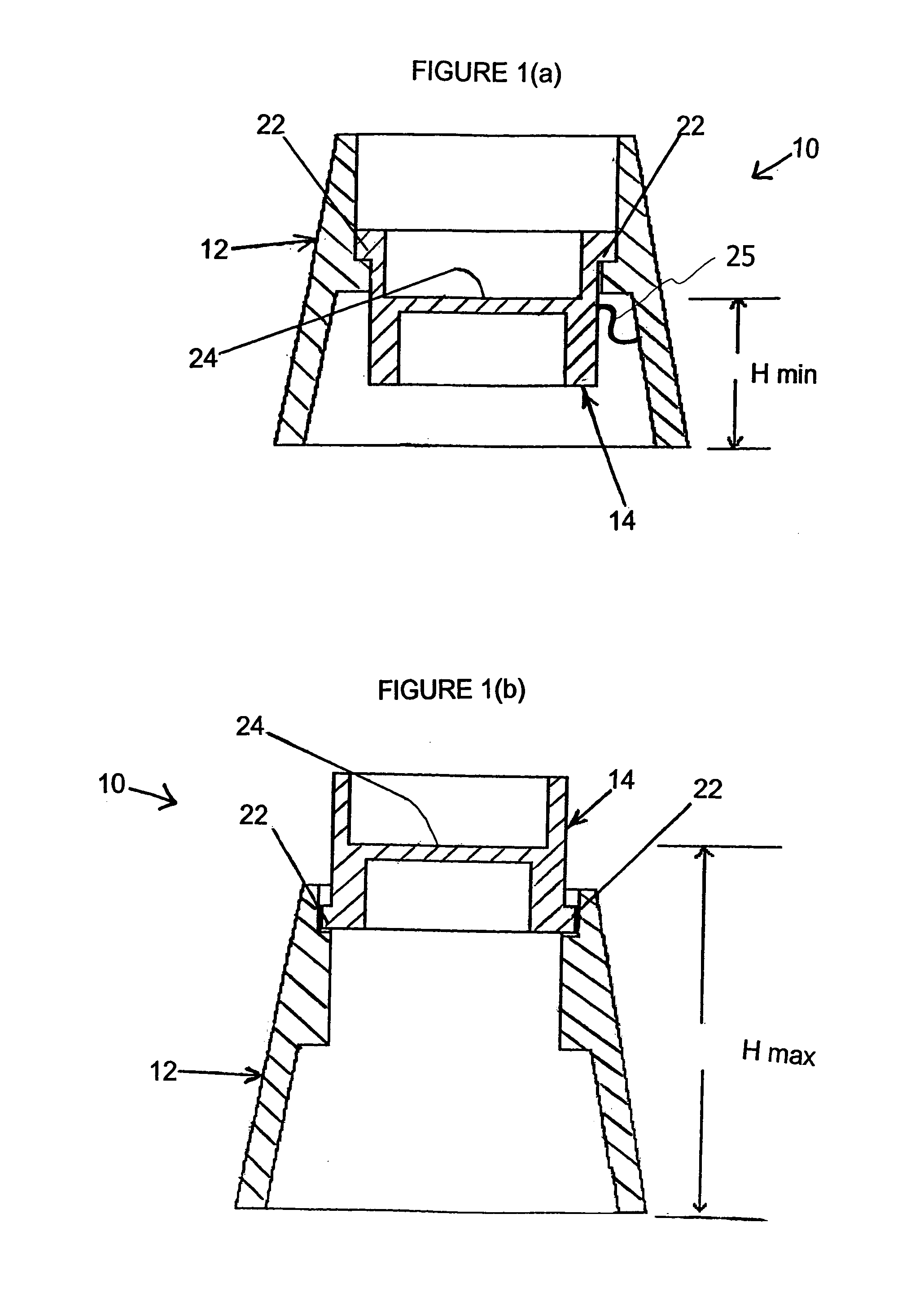
[0052]First Embodiment—Overview Referring to FIGS. 1(a)–1(b), a height-adjustable support apparatus, according to the present invention, is shown generally at 10. The support apparatus 10 generally includes a base 12 which is provided to rests on a floor surface or similar substrate (e.g., a floor, a counter top, a table, etc.), and a cradle 14, which may be selectively and adjustably engaged with, and supported by the base 12 in various orientations and arrangements corresponding to different heights of a support platform 24.

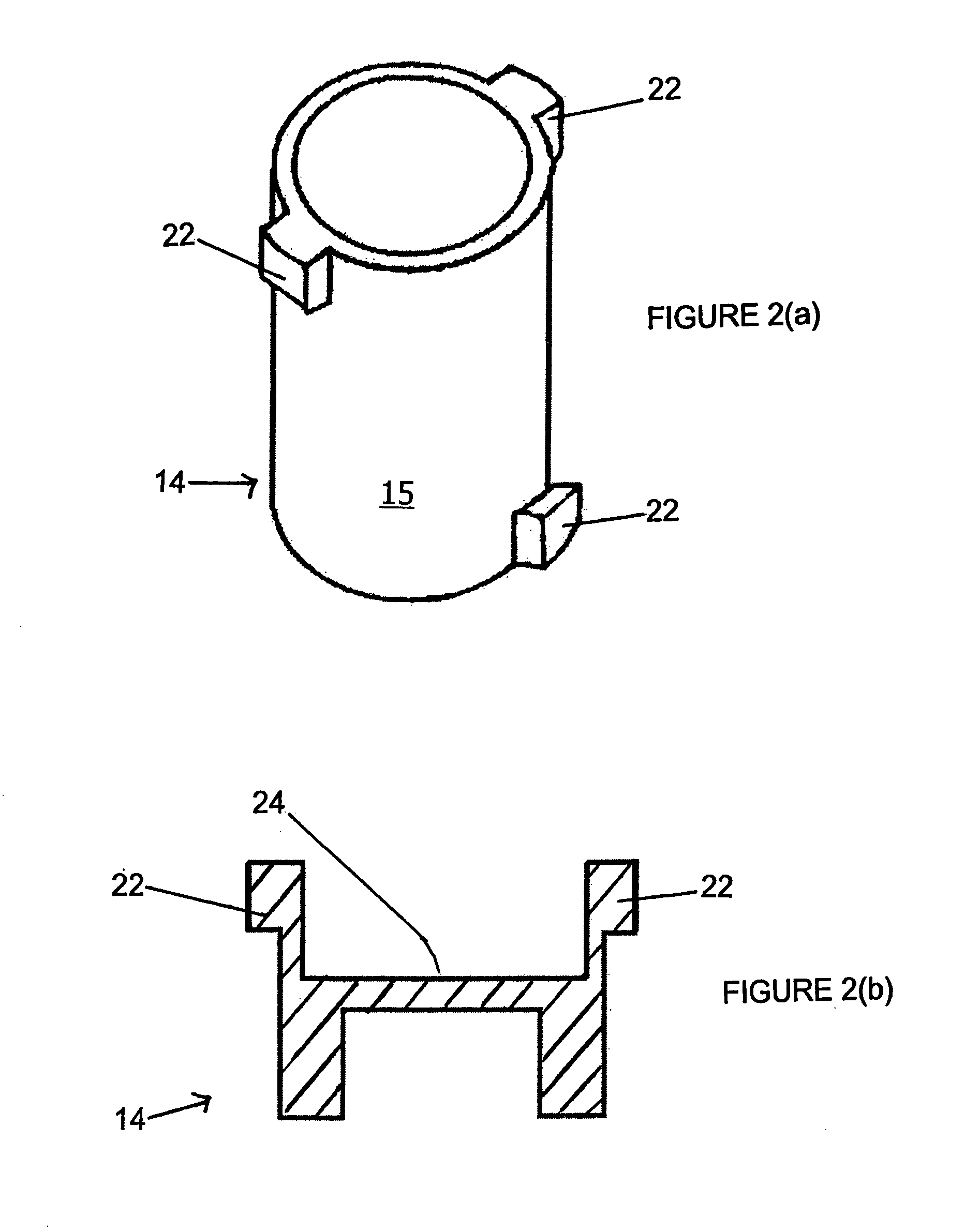
[0053]In this first embodiment of the apparatus 10, the base 12 has a number of substantially vertical grooves 20 (FIGS. 3a, 3b) defined in an inner surface thereof to receive cradle projections. Correspondingly, the cradle 14 has a number of projections 22 extending outwardly thereon, which are provided to fit in and operatively engage the grooves.

[0054]The cradle 14 also includes a generally flattened, substantially horizontal integral support platform 24 ext...

second embodiment

[0085

[0086]Overview

[0087]According to a second embodiment of the invention, as seen in FIGS. 5(a) and 5(b), a support apparatus 210 again includes two parts formed of appropriate material, i.e., a base 40 and a cradle 42, which may be selectively, operatively engaged with the base in various positions corresponding to different support heights. As depicted, the cradle 42 may be a substantially flat member, while both the cradle and the base 40 may have substantially horizontally aligned projections 44 and grooves 46 provided therewith and which are adapted to be engaged with the projections and grooves on the other part. Although not shown, a rubber band or other elastic member, such as the member 25 in the first embodiment, could be used to join the cradle 42 and the base 40 together.

[0088]The Base

[0089]Particularly, the base 40 (again) may be formed as a hollow member having a large central opening 48 for receiving the cradle 42, and a truncated conical outer shape. The inner surf...

third embodiment

[0097]Overview

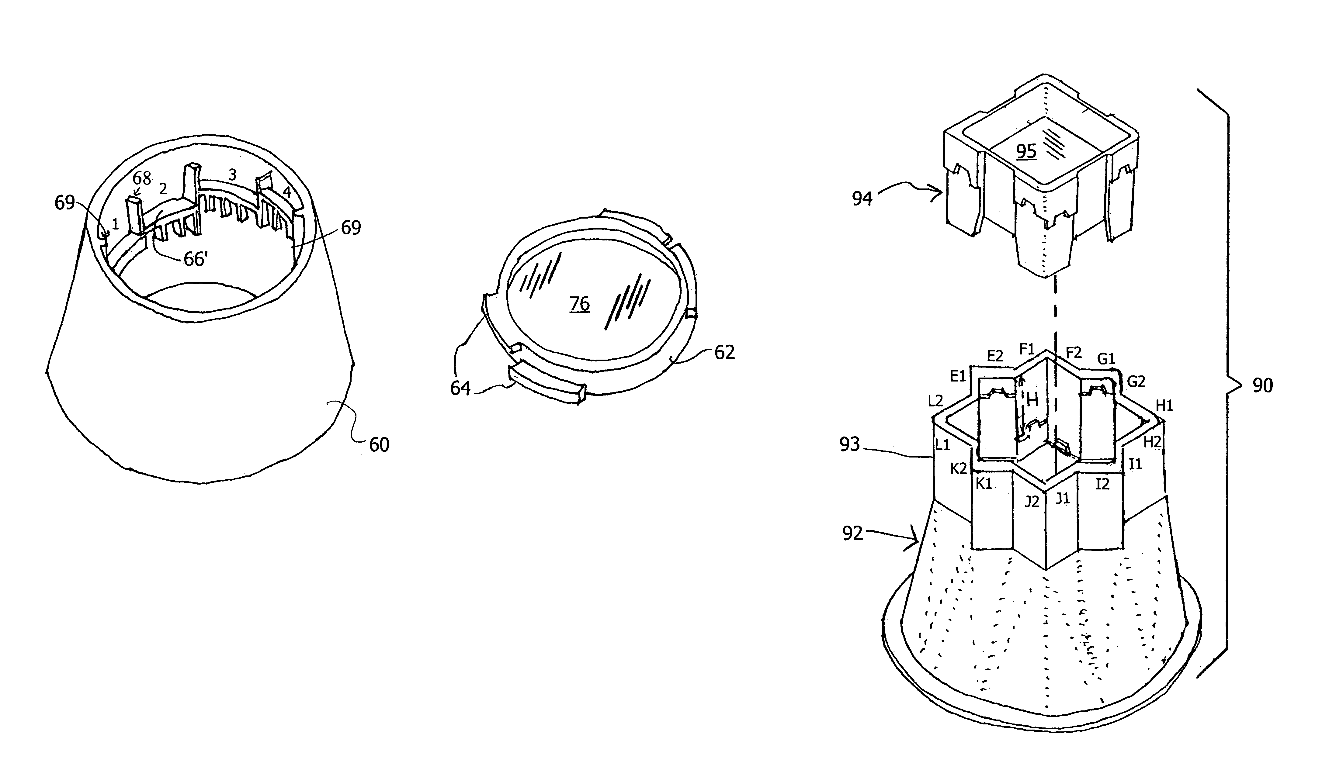
[0098]According to a third embodiment of the invention, as seen in FIGS. 6(a)-7, a support apparatus again includes two parts, i.e., a base 60 and a cradle 62 which may be selectively, operatively engaged with the base in various positions corresponding to different support heights.

[0099]The third embodiment includes features and functions similar to those of the first two embodiments. As depicted, the cradle 62 may be a substantially flat member, with pairs of substantially horizontally extending projections 64 that are slightly offset relative to each other in both circumferential and vertical directions (a so-called bi-wing arrangement), and a support platform 76. During use, both pairs of the projections 64 engage adjacent levels of groove footholds 66′ to strongly support the cradle thereon.

[0100]The support platform 76, as depicted, is somewhat recessed on its upper face, while its lower face would be similarly recessed but with a different size and / or shape for ...


PUM


Abstract

An adjustable support apparatus, for elevating a furniture article, includes a base and a cradle which operatively engages the base so as to be supported thereby. The cradle includes a substantially horizontal support platform adapted to support a portion of a furniture item thereon. One of the base and the cradle has a plurality of projections extending outwardly thereon, and the other of the base and the cradle has a plurality of recesses, which mate with the projections when the base and the cradle are operatively engaged. The base and the cradle are rotatably adjustable relative to one another, to variously engage the projections and recesses and thereby establish multiple different height positions of the cradle support platform. The apparatus is used to adjustably raise the height level of a furniture article, particularly a bed, by placing individual supports according to the invention underneath the respective leg posts of the furniture article.

Description

CROSS-REFERENCE TO RELATED APPLICATIONS[0001]The present application claims priority under 35 USC 119 based on U.S. provisional application Ser. No. 60 / 442,997, filed Mar. 11, 2003. The disclosure of U.S. provisional application Ser. No. 60 / 442,997 is hereby incorporated by reference.BACKGROUND OF THE INVENTION[0002]1. Field of the Invention[0003]The present invention relates to an adjustable support for use in elevating a bed or other furniture item above a floor surface or similar substrate, by placing the support underneath the leg(s) of the bed or other furniture item. More particularly, the invention relates to such a support having a simplified, low-cost structure which can easily be adjusted between multiple stepped positions, and which is capable of securely supporting a furniture item at a desired level during use.[0004]2. Description of the Background Art[0005]There are many known devices for raising the height level of a furniture item by positioning the devices such that...

Claims


Application Information

Patent Timeline
Patent Type & Authority Patents(United States)
IPC IPC(8): A47C19/04A47C19/00F16M11/20F16M11/24A47B91/02
CPCA47B91/02A47C19/024A47C19/045F16M11/22F16M7/00F16M11/24Y10T403/32451Y10T16/193
Inventor SOH, SUNG KUK
Owner SOH SUNG KUK
Why Eureka
Try Eureka