
Connecting arrangement for coolant lines

a technology of connecting arrangement and coolant line, which is applied in the direction of pipe elements, compression machines with non-reversible cycles, lighting and heating apparatus, etc., can solve the problem of complex assembly or disassembly of them

Active Publication Date: 2005-05-17
CONTITECH TECHNO CHEM
View PDF18 Cites 20 Cited by
  • Summary
  • Abstract
  • Description
  • Claims
  • Application Information

AI Technical Summary

Benefits of technology

[0004]It is an object of the invention to provide a connecting arrangement of the kind referred to above configured with the most simple means so that a simple assembly or disassembly of the connecting arrangement is possible also in tight spaces. It is a further object of the invention to provide a tight sealing of the connecting arrangement at pressures up to 145 bar and at temperatures up to 180° C.
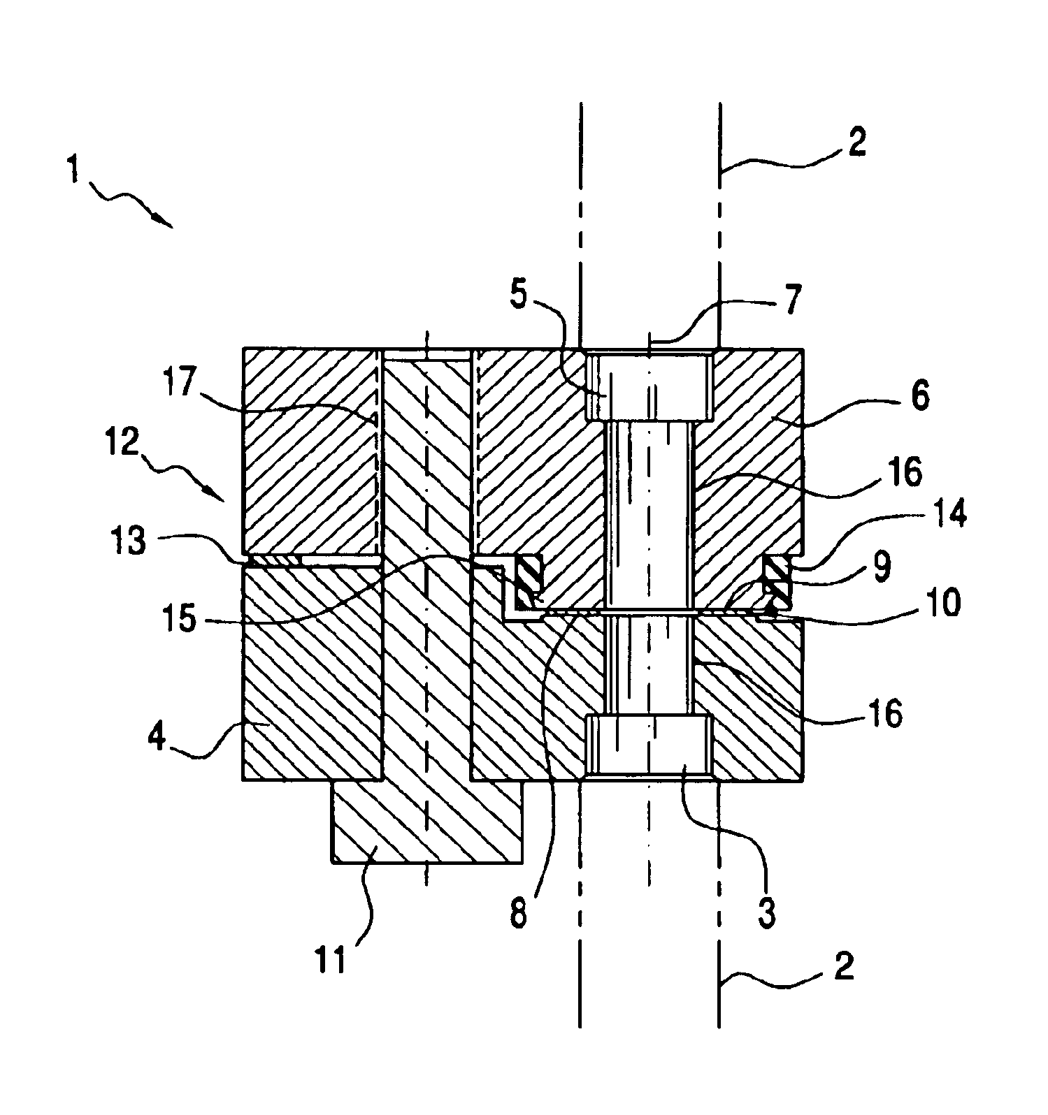
[0008]The invention is especially characterized in that the introduction of force when joining the coupling pieces takes place eccentrically by only the single screw. A lever action is achieved by the non-compressible form body at the intermediate space of the coupling pieces and leads to an intense pressing together of the sealing ring. In this way, the tightness of the connecting arrangement is ensured. Preferably, at least one coupling piece is already so formed that the non-compressible form body is configured as a component of the coupling piece. The non-compressible form body can be configured as a single piece with the coupling piece.
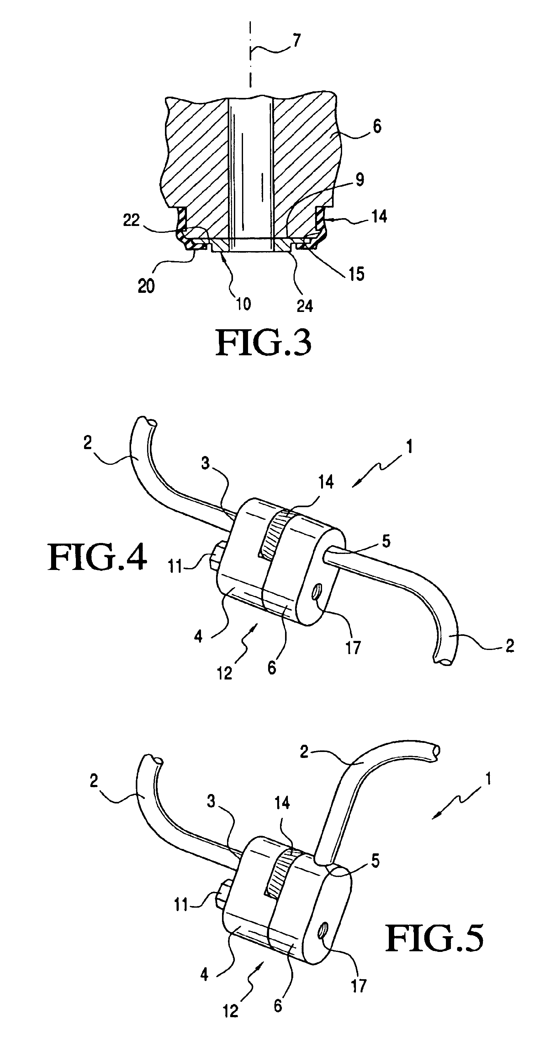
[0012]It is, however, also practical to arrange the line endpieces at an angle to each other and preferably at right angles to each other. A connecting arrangement configured in this way can be advantageously used in very tight spaces.

Problems solved by technology

A connecting arrangement of this kind has the disadvantage that the assembly or disassembly thereof is very complex when only a limited space is available.

Method used


Image

  • Connecting arrangement for coolant lines
  • Connecting arrangement for coolant lines
  • Connecting arrangement for coolant lines

Examples


Embodiment Construction

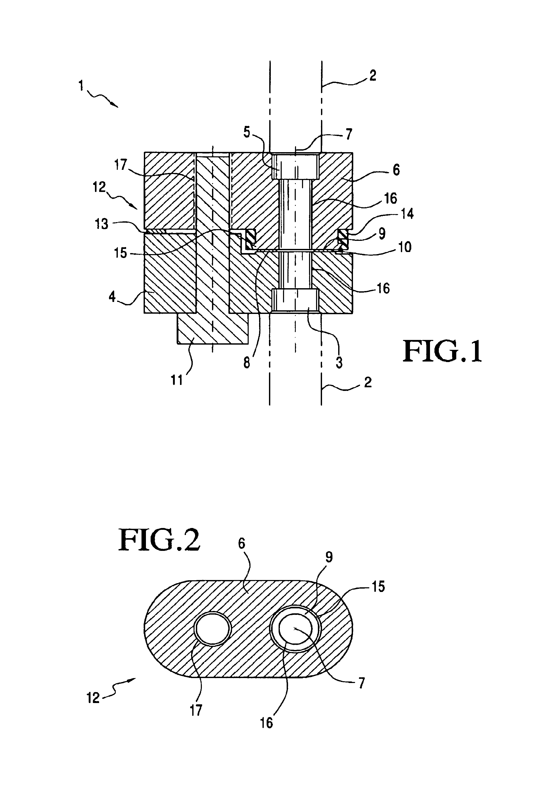
[0019]The connecting arrangement 1 shown in FIG. 1 is for coolant lines 2 and comprises a first coupling piece 4 and a second coupling piece 6. The first coupling piece 4 is connected tightly to a first line endpiece 3 and the second coupling piece 6 is tightly connected to a second line endpiece 5. The connection between the coupling pieces (4, 6) and the endpieces (3, 5) is non-detachable. Each of the coupling pieces (4, 6) includes a bore 16 in which the corresponding one of the line endpieces (3, 5) is fitted in. The bore 16 has, at the same time, the function of a connecting channel. Both coupling pieces 4 and 6 are threadably fastened to each other by a single screw 11. A bore 17 in the coupling piece 6 has an internal thread. Because of the threaded connection, the line endpieces (3, 5) are alignedly connected to each other via the bore 16 along an axis 7. The two coupling pieces 4 and 6 furthermore each include a radially extending sealing surface 8 and 9 on the end facing t...


PUM


Abstract

A connecting arrangement for coolant lines includes a first coupling piece, connected seal-tight to a first line endpiece, and a second coupling piece, connected seal-tight to a second line endpiece. The coupling pieces each have radially extending sealing surfaces on the side facing toward the other coupling piece. A sealing ring is mounted between the sealing surfaces. The coupling pieces are joined to each other via a screw arranged laterally offset from the sealing surfaces so the line endpieces connect to each other via respective bores in the coupling pieces. A form body between the coupling pieces arranged at a spacing from the screw on the side facing away from the sealing surfaces is configured so a lever action occurs when the coupling pieces are joined to each other leading to a uniform pressing together of the sealing ring between the sealing surfaces of the coupling pieces.

Description

CROSS REFERENCE TO RELATED APPLICATION[0001]This application claims priority of European patent application no. 03002425.1, filed Feb. 5, 2003, the entire content of which is incorporated herein by reference.BACKGROUND OF THE INVENTION[0002]German patent publication 299 08 541 discloses a connecting arrangement for coolant lines, especially, for motor vehicle climate control systems operated with CO2. In this connecting arrangement, the line endpieces of two coolant lines are each provided with a coupling piece. Both coupling pieces each include a radially running sealing surface on the end facing toward the other coupling piece. A metallic flat ring is seated between the sealing surfaces and has a peripheral recessed portion. The metallic flat ring, which is provided with a peripherally extending recessed portion, is pressed together by the threaded fastener of the two coupling pieces and ensures the necessary axial sealing of the connecting arrangement. The threaded connection of ...

Claims


Application Information

Patent Timeline
Patent Type & Authority Patents(United States)
IPC IPC(8): F16L41/08B60H1/32F25B1/00F16L23/16F25B41/00
CPCF16L23/20B60H1/00571F16L41/086F25B2309/061
Inventor WILDERMUTH, ANDREASEISMANN, MIKE
Owner CONTITECH TECHNO CHEM
Learn More