
Crash energy absorption assembly for a motor vehicle

a technology for motor vehicles and energy absorption assemblies, which is applied in the direction of bumpers, vehicle cleaning, roofs, etc., can solve problems such as inability to be easily installed, and achieve the effect of reducing vibration between elements

Inactive Publication Date: 2005-05-17
ARCONIC TECH LLC
View PDF25 Cites 56 Cited by
  • Summary
  • Abstract
  • Description
  • Claims
  • Application Information

AI Technical Summary

Benefits of technology

[0009]The modular front end is based on the concept of “functionally decoupling” the several sub-modules or sub-assemblies from each other. In front end assembly techniques currently practiced in the art, the various elements or components of the front end are substantially interconnected or related. In contrast, the modular front end of the present invention has the various sub-assemblies comprising the front end substantially functionally isolated from one another. The separate functions of the sub-assemblies, which will be discussed hereinafter, are substantially independent from one another allowing any one sub-module or sub-assembly to be individually replaced without affecting the other sub-modules or sub-assemblies. This allows the sub-modules or sub-assemblies to be comprised of smaller and lighter individual components or parts, which is not easily possible in the “interrelated” front end structures generally found in the prior art. The use of separate and distinct sub-modules or sub-assemblies in the modular front end allows the overall size of the modular front end to be reduced because the sub-assemblies may be compact tightly within the modular front end. The smaller front end made possible by the modular front end of the present invention improves the overall driving and handling characteristics of the motor vehicle. For example, the smaller front end is lower in profile than those currently known in the art, which improves the driver's view of the road and aids the driver in performing routine vehicle operations such as parking, turning, etc.
[0012]The bulkhead may define at least one hollow cavity formed therein for increasing strength and rigidity of the bulkhead. The at least one hollow cavity may be filled with a cast-in-place core, preferably an aluminum foam core. The hollow cavity may also be filled with polymeric foam. The at least one structural member may comprise a pair of door hinge pillars attached to attachment mounts located at opposite ends of the bulkhead. The at least one structural member may also comprise a pair of rocker panels attached to a bottom end of the bulkhead opposite the door hinge pillars. Additionally, the at least one structural member may comprise a pair of windshield support pillars attached to a top end of the bulkhead. The at least one structural member may further comprise a windshield cross member attached to the top end of the bulkhead between the windshield support pillars.
[0014]The drive train assembly generally comprises a drive train support and a power train assembly attached to the drive train support. The drive train support comprises a pair of elongated support members that are configured for attachment, preferably by mechanical means, to a bulkhead of the motor vehicle. By mechanical attachment or means, it is meant that mechanical fasteners, such as nuts and bolts, rivets, and the like are preferably used to attach the various elements described in this disclosure, and may include rubber isolation mounts (i.e., bushings), where necessary, to minimize vibration between elements. The drive train support further comprises a cross member interconnecting the support members. The support members are further configured to support the power train assembly such that the power train assembly is cantilevered from the support members and bulkhead forward of the cross member.

Problems solved by technology

This allows the sub-modules or sub-assemblies to be comprised of smaller and lighter individual components or parts, which is not easily possible in the “interrelated” front end structures generally found in the prior art.

Method used


Image

  • Crash energy absorption assembly for a motor vehicle
  • Crash energy absorption assembly for a motor vehicle
  • Crash energy absorption assembly for a motor vehicle

Examples


Embodiment Construction

[0050]For purposes of the description hereinafter, the terms “upper”, “lower”, “right”, “left”, “vertical”, “horizontal”, “top”, “bottom”, and derivatives thereof shall relate to the invention, as it is oriented in the drawing figures. However, it is to be understood that the invention may assume various alternatives and step sequences, except where expressly specified to the contrary. It is also to be understood that the specific elements and processes illustrated in the drawings, and described in the following specification, are simply exemplary embodiments of the invention. Hence, specific dimensions and other physical characteristics related to the embodiments disclosed herein are not to be considered alimiting.

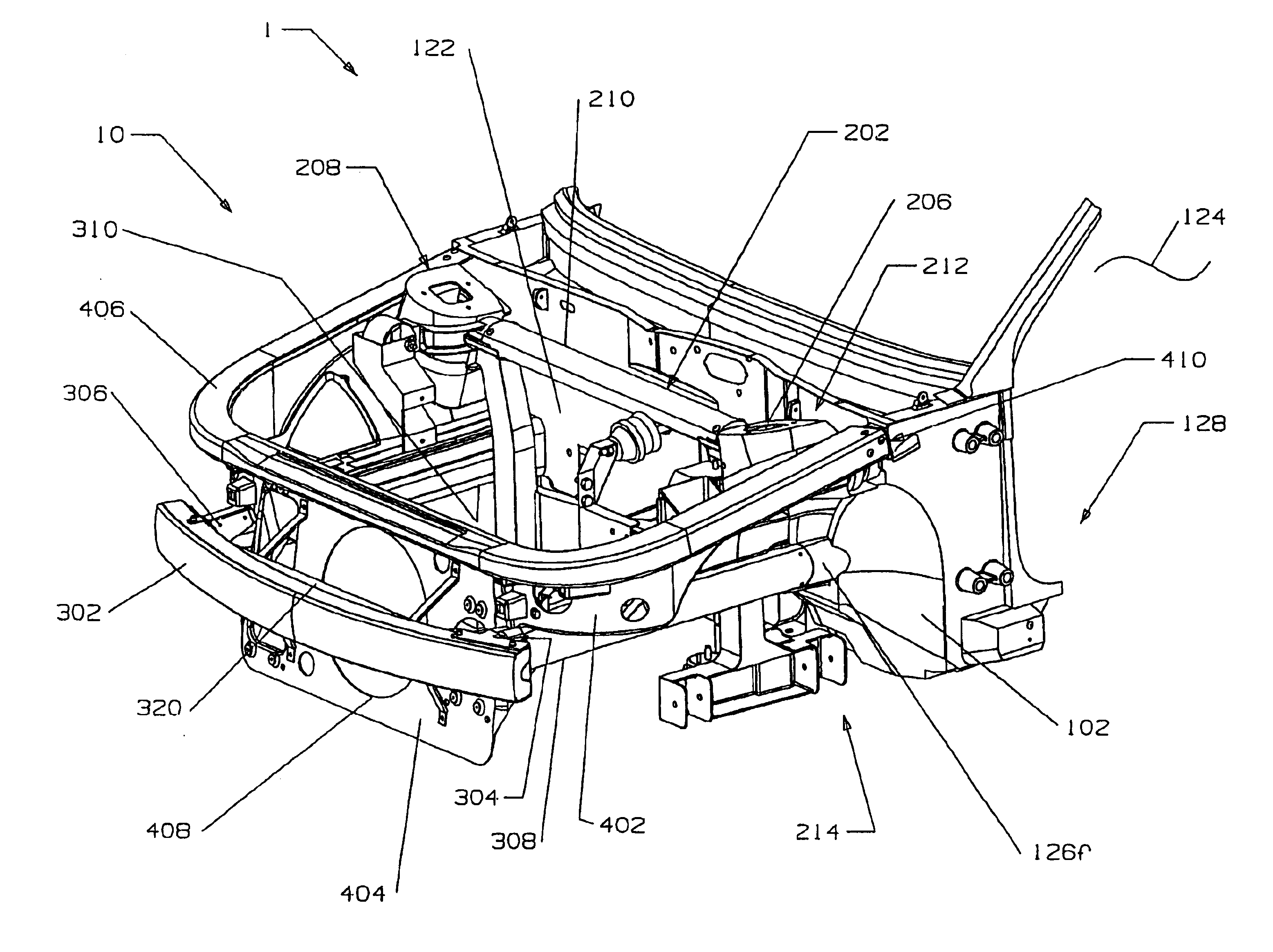
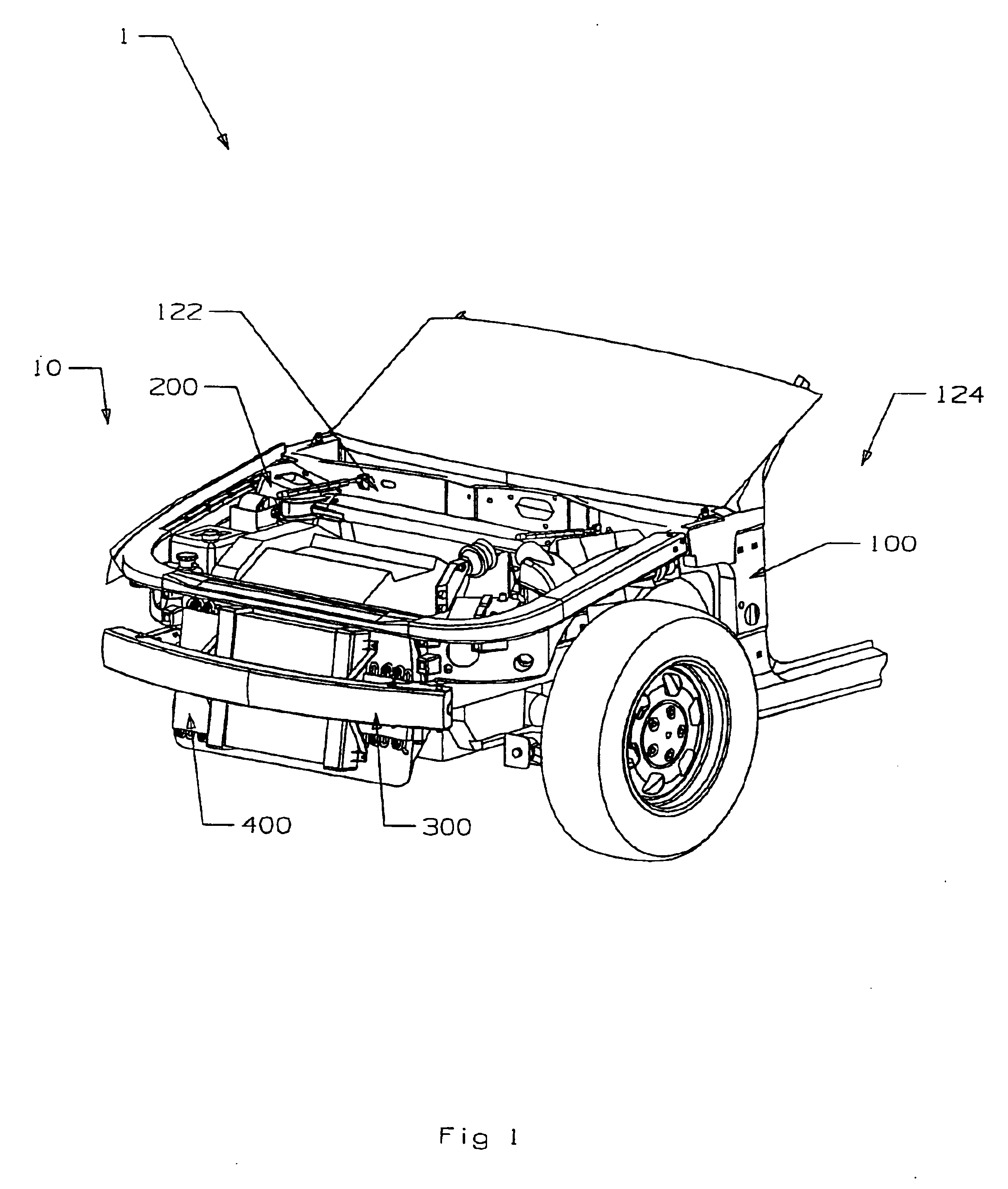
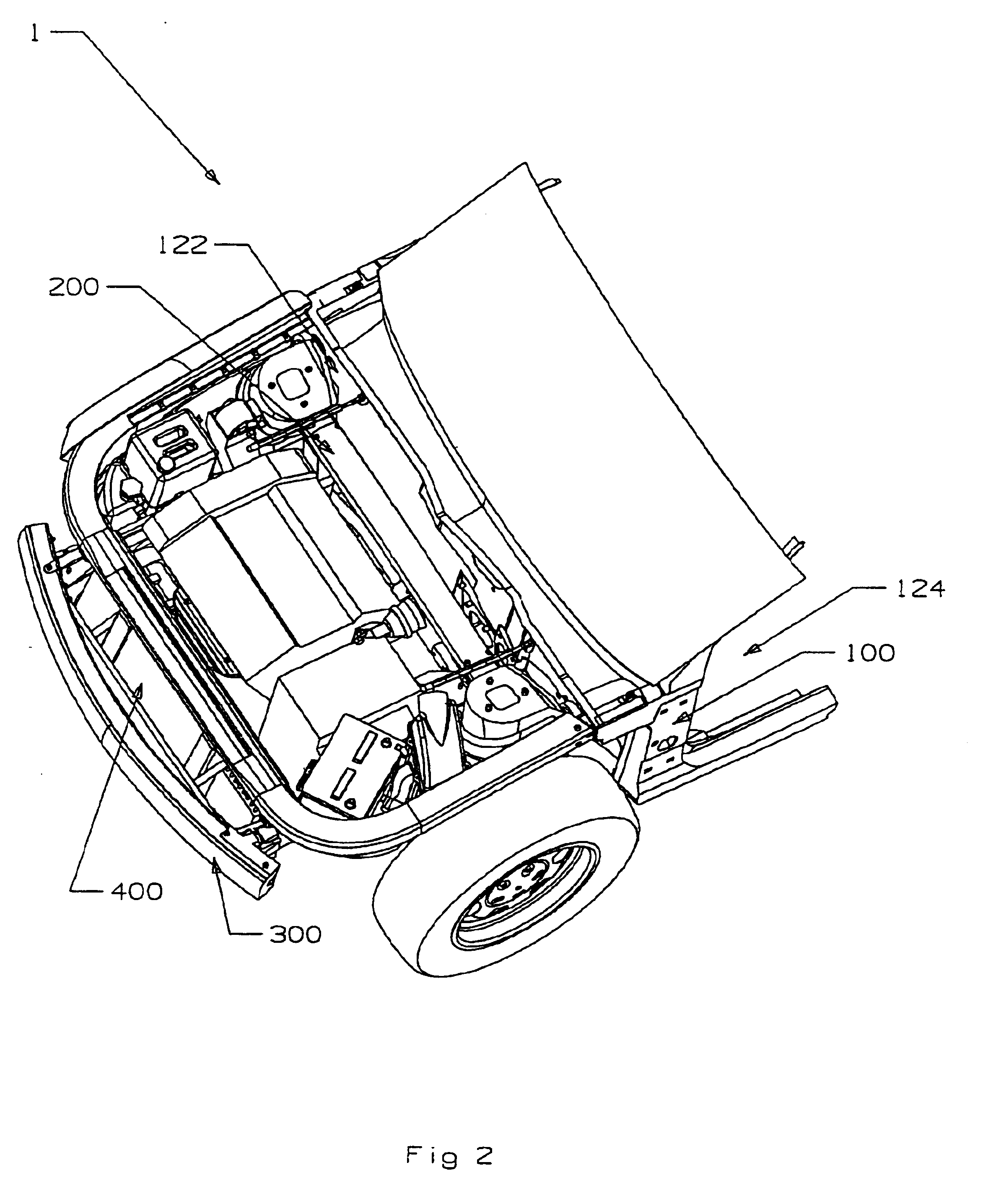
[0051]Referring to FIGS. 1 and 2, a motor vehicle 1 comprising a modular front end 10 in accordance with the present invention is shown. Only the front portion of the motor vehicle 1 is shown, but the remainder of the motor vehicle 1 is conventional. The modular front end...


PUM


Abstract

The modular front end forms the front portion of a motor vehicle. The modular front end includes a bulkhead defining a plurality of integrally formed attachment mounts. A drive train assembly carrying at least an engine of the motor vehicle is attached to the bulkhead at the attachment mounts. A crash energy absorption assembly is attached to the attachment mounts on the bulkhead and generally extends around the drive train assembly. An apron assembly is attached to the bulkhead at the attachment mounts and is generally positioned above the drive train assembly and crash energy absorption assembly.

Description

CROSS REFERENCE TO RELATED APPLICATIONS[0001]This application claims the benefit of U.S. Provisional Patent Application Serial No. 60 / 329,802, filed Oct. 16, 2001, and entitled “Modular Front End For Passenger Cars And Light Trucks, Joining An Integrated Drive Train Module, Apron-Cum Energy Module And Crash Energy Management Module To An Integrated Structural Cowl”, the full disclosure of which is incorporated herein by reference.BACKGROUND OF THE INVENTION[0002]1. Field of the Invention[0003]The present invention relates generally to motor vehicles, such as passenger cars and light trucks. More particularly, the present invention relates generally to a multi-component front end for a motor vehicle, which advances the methods by which motor vehicles are assembled.[0004]2. Description of Related Art[0005]Currently, the front ends of most motor vehicles are built into the vehicle body one piece or component at a time. The installation of literally hundreds of different components in t...

Claims


Application Information

Patent Timeline
Patent Type & Authority Patents(United States)
IPC IPC(8): B60K5/12B62D65/00B62D25/08B60K17/00B62D65/04B62D21/15B60R19/03B60R19/24B60R19/34B60R21/34B60R19/18
CPCB60K5/12B60K17/00B60R19/03B60R19/34B62D65/04B62D21/152B62D25/082B62D25/084B62D25/088B60R2019/1806B60R2021/343B60R2019/182
Inventor SEKSARIA, DINESH C.COBES, JOHN W.MURPHY, THOMAS J.
Owner ARCONIC TECH LLC
Learn More