Compressor with Z-plate

a compressor and plate technology, applied in the direction of machines/engines, rotary/oscillating piston pump components, liquid fuel engines, etc., can solve problems such as degrading compression performance, and achieve the effect of promoting the improvement of compressor performance and preventing abrasion of the van

Inactive Publication Date: 2005-05-17
LG ELECTRONICS INC
View PDF3 Cites 9 Cited by
  • Summary
  • Abstract
  • Description
  • Claims
  • Application Information

AI Technical Summary

Benefits of technology

[0015]Therefore, an object of the present invention is to provide a compressor with a Z-plate that is capable of preventing abrasion of a vane or a bearing plate as well as a fluid leakage or an impact noise by stabilizing a behavior of the vane being in contact with a Z-plate, thereby promoting improvement of performance of a compressor.

Problems solved by technology

This would result in a degradation of a compression performance.

Method used


Image

  • Compressor with Z-plate
  • Compressor with Z-plate
  • Compressor with Z-plate

Examples


Embodiment Construction

[0026]Reference will now be made in detail to the preferred embodiments of the present invention, examples of which are illustrated in the accompanying drawings.

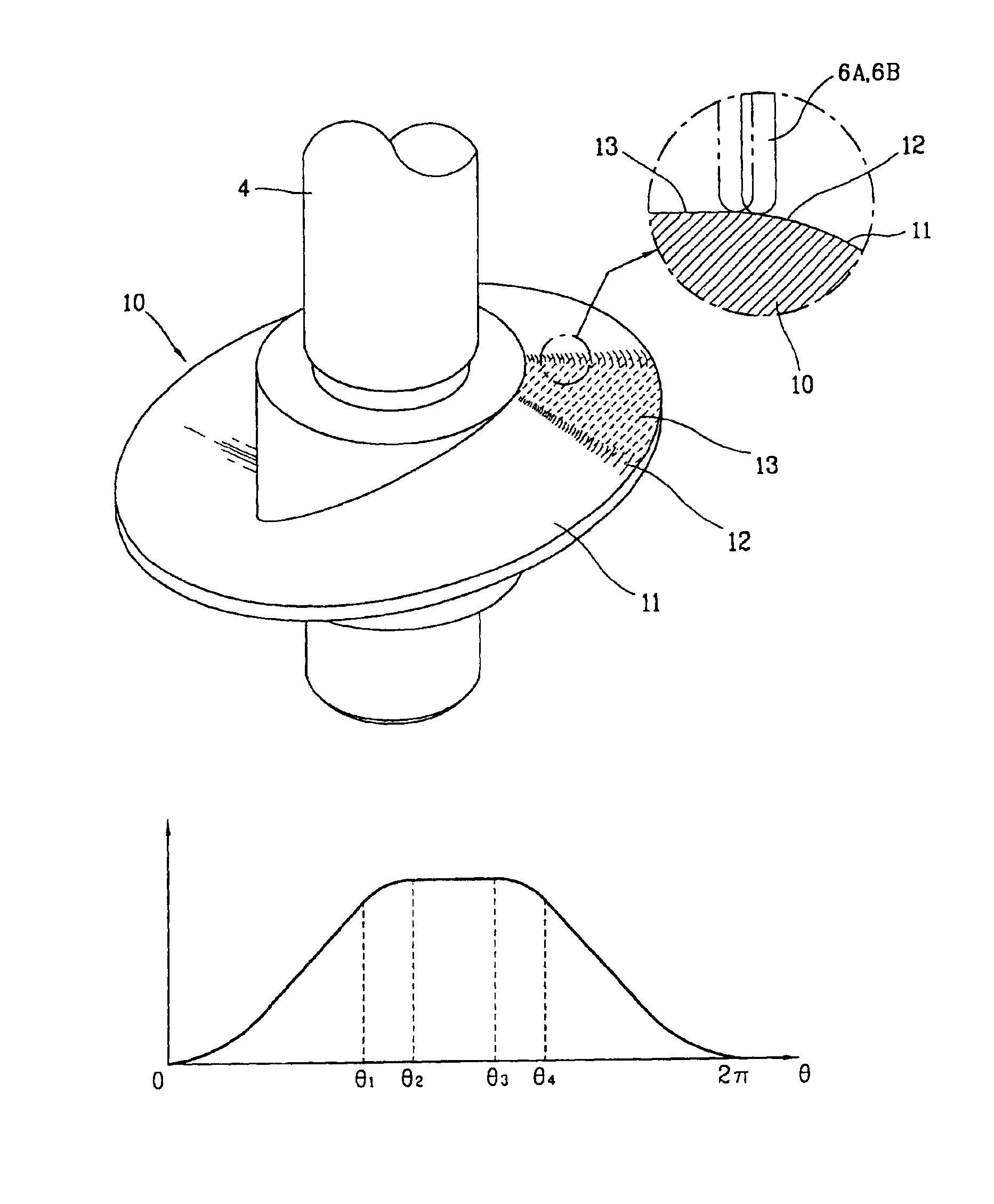
[0027]FIG. 4 is a perspective view of a Z-plate of a compressor with a Z-plate in accordance with the present invention, and FIG. 5 is a graph showing a development of a cam surface of the Z-plate of the compressor in accordance with the present invention.

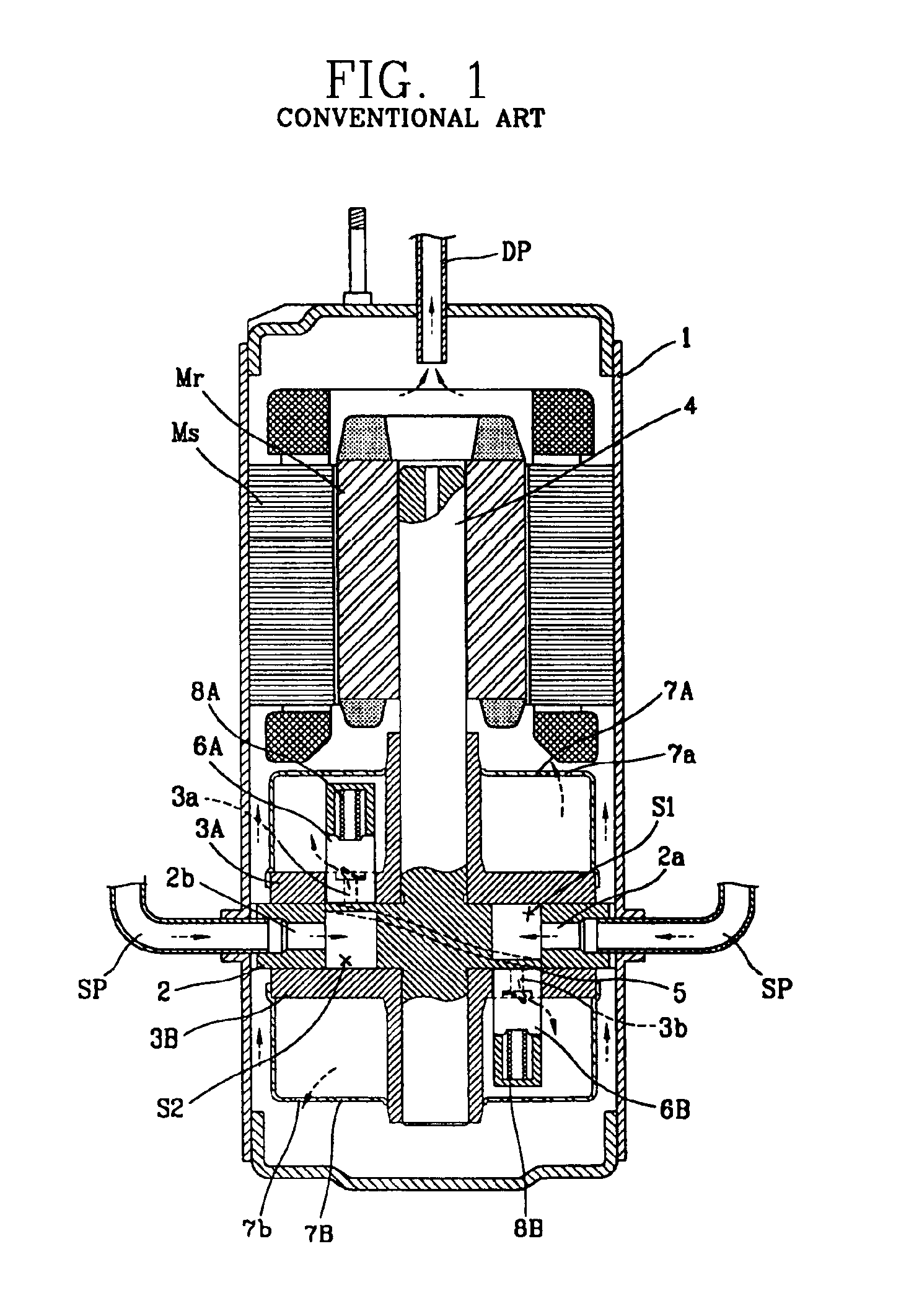
[0028]With reference to FIG. 1, a compressor with a Z-plate in accordance with the present invention includes: a cylinder 2 coupled at one side of an electric mechanism unit and fixed at a casing 1, first bearing plate 3A and second bearing plate 3B fixed at the an upper surface and a lower surface of the cylinder 2 and forming an inner space of the cylinder 2 together; a rotational shaft 4 coupled at the electric mechanism unit and penetratingly coupled to the bearing plates 3A and 3B so as to transfer a driving force of the electric mechanism unit to a compression mechani...


PUM


Abstract

A compressor is provided which minimizes impact noise and abrasion between a Z-plate of the compressor and vanes formed in the compressor. Ends of the vanes formed in the compressor contact sides of the Z-plate, and the motion and surface configuration of the Z-plate cause the vanes to move reciprocally and to section compression spaces within the compressor into a suction area and a compression area. Due to the curvature of the surfaces of the Z-plate, the vanes remain in constant contact with the surface of the Z-plate, which allows for smooth transition phases and a subsequent reduction in impact noise and abrasion between the vanes and the Z-plate.

Description

TECHNICAL FIELD[0001]The present invention relates to a compressor with a Z-plate, a kind of rotary compressor, and, more particularly, to a compressor with a Z-plate in which a plane portion provided at both top dead centers of a Z-plate meet other curved portion with a curved line.BACKGROUND ART[0002]In general, a compressor is a device for converting a mechanical energy into a compression energy of a fluid. And, depending on a compression method, a freezing compressor is classified into a reciprocating compressor, a scroll compressor, a centrifugal compressor and a rotary compressor.[0003]The applicant of the present invention has filed an application for a development of a compressor with Z-plate with a novel conception, that can be classified as a rotary compressor, which was laid open on May 7, 2001 with a Korean Patent Publication No. 2001-0035687.[0004]The compressor with a Z-plate in accordance with a conventional art will now be described with reference to FIG. 1.[0005]The...

Claims


Application Information

Patent Timeline
Patent Type & Authority Patents(United States)
IPC IPC(8): F01C21/00F01C21/08F04C18/356F04C23/00
CPCF01C21/08F04C18/3568F04C23/008
Inventor YANG, KWANG-SIKSA, BUM-DONG
Owner LG ELECTRONICS INC
Why Eureka
Try Eureka