Ablation instrument having a flexible distal portion

a technology of flexible distal portion and catheter, which is applied in the field of catheter systems, can solve the problems of poor lesion formation, difficult maneuverability of the distal portion of the catheter, and difficulty in properly positioning the distal portion of the catheter, and achieve the effect of improving the mechanical advantag

Inactive Publication Date: 2005-05-17
AFX +1
View PDF7 Cites 464 Cited by
  • Summary
  • Abstract
  • Description
  • Claims
  • Application Information

AI Technical Summary

Benefits of technology

[0007]Accordingly, it is a general object of the present invention to provide a catheter system which resolves the above-identified problems. Another object of the present invention is to provide a catheter system which ensures proper placement of an a

Problems solved by technology

Proper placement of an ablation device is exasperated by the fact that some ablative energy technologies require energy transmission conduits which are bulky, or otherwise constructed from materials less flexible, making the distal portion of the catheter difficult to properly position.
For example, distal portions of optical fiber or microwave based ablation systems, or cathet

Method used


Image

  • Ablation instrument having a flexible distal portion
  • Ablation instrument having a flexible distal portion
  • Ablation instrument having a flexible distal portion

Examples


first embodiment

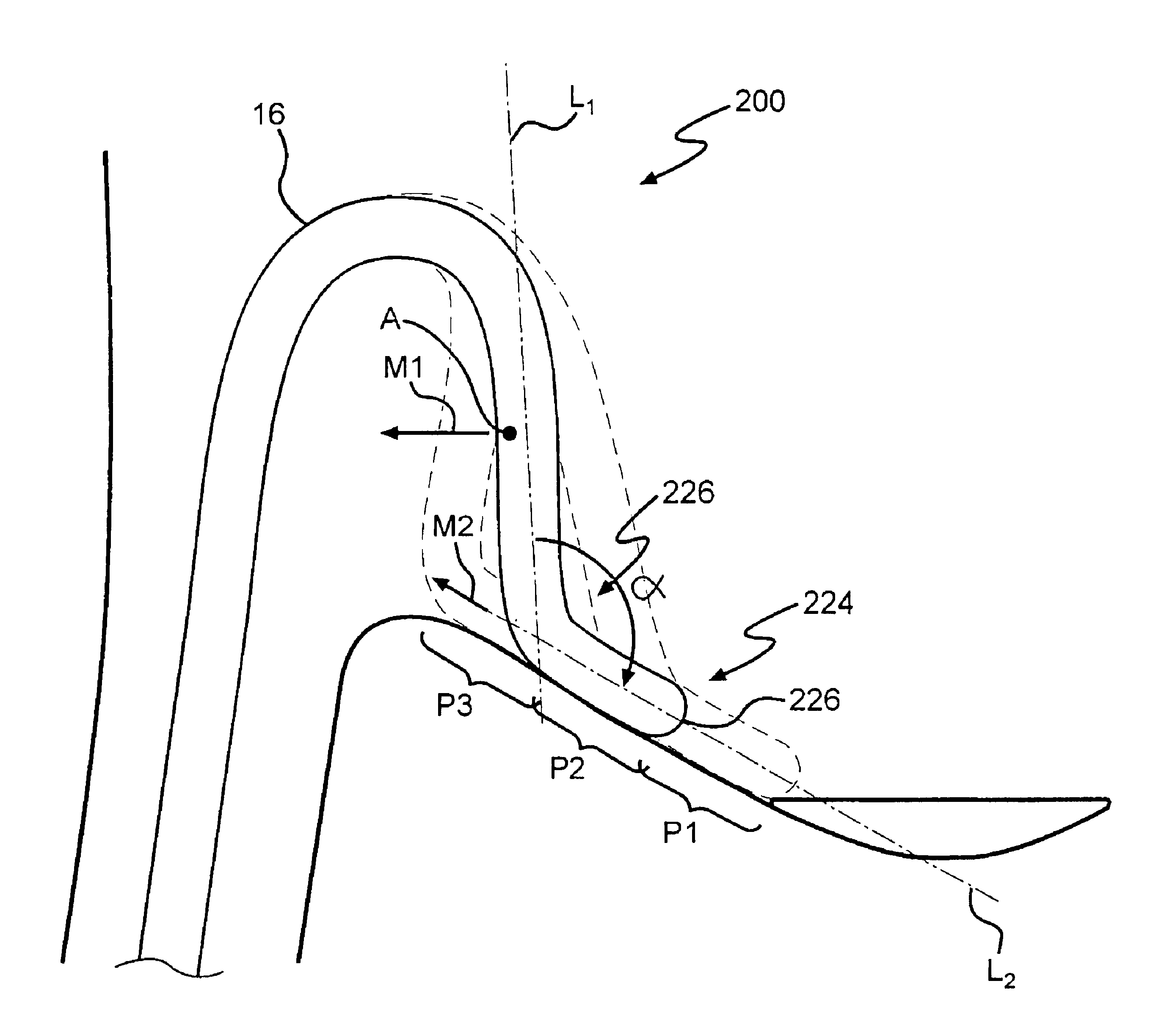
[0066]Now turning also to FIGS. 5A, 6 and 9, catheter 200 incorporating flexible means 226 will be discussed in more detail. FIG. 5A depicts a catheter system 200 incorporating a flexible means 226. As shown, catheter 200 comprises steering system 102 located proximal to flexible means 226. While FIG. 5A depicts steering system 102A, any steering system 102 discussed, or otherwise contemplated herein, may be utilized as required by the specific configuration of catheter 200.

[0067]Flexible means 226 comprises a coil spring element 226A which, upon application of an external force upon distal portion 224 by target tissue 10 allows distal portion 224 to deflect to a position as shown in dashed-line. As will become readily apparent, as catheter system 200 is further manipulated, movement of the ablation device upon target tissue 10 along a desired path is achieved through operation of means 226.

[0068]With reference now made to FIG. 5B, another embodiment of catheter system 200 is shown ...

second embodiment

[0069]Alternatively, with reference to FIG. 6, a catheter system 200 incorporating a flexible portion 226B is shown. Flexible portion 226B allows for the same functionality as portion 226A, discussed immediately above. More specifically, flexible portion 226B is constructed from any suitable biocompatible material allowing for the desired deflection of distal portion 224 upon contact and application of an external force thereon, as discussed above. Alternatively, flexible portion 226B may be an extension of member 112, as part of steering system 102A, beyond ring member 114. Generally, flexible portion 226B extends from about 0.5 cm. to about 2.0 cm. beyond ring member 114, however this depends directly on the specific configuration of the ablation device utilized.

[0070]With reference now to FIGS. 7A and 7B, another embodiment of steering system 102 will be discussed. Steering system 102C is similar to steering system 102B, however lacks distal ring member 114 and further includes a...


PUM


Abstract

An ablation instrument having a flexible portion at or near the distal portion of the instrument, is provided. The instrument includes an elongated tubular member having a steerable distal end configured to deflect, or otherwise direct, and properly position at least a portion of the distal portion, comprising an ablation device, during an ablation procedure. The instrument further includes a deflectable member which cooperates with the steering system allowing for the proper placement of the ablation device adjacent or proximate to the target tissue surface. The steering system may alternatively be incorporated into a separate guiding catheter as part of the catheter system.

Description

BACKGROUND OF THE INVENTION[0001]1. Field of Invention[0002]The present invention relates generally to catheter systems used in diagnosis and treatment of various body tissues and, more specifically, to steering systems incorporated into catheter systems for ablating cardiac tissue in the treatment of electrophysiological diseases.[0003]2. Description of the Related Art[0004]As is well know, catheters provide medical professionals access to various interior regions of the human body, in a minimally invasive manner, in support of diagnosis and treatment. Catheters allow such professionals to place one or more medical instruments, pharmacological agents or other matter at a target tissue site. For example, in cardiac procedures in support of diagnosis and treatment of atrial fibrillation, catheters provide access to various chambers of the heart, carrying ablation devices which translate therein to such sites for ablation of specific cardiac tissue associated with atrial fibrillation....

Claims


Application Information

Patent Timeline
IPC IPC(8): A61B18/18A61B18/14A61B19/00A61B17/00
CPCA61B18/1492A61B18/18A61B18/1815A61B2019/4054A61B2017/003A61B2018/1861A61B2090/0454
Inventor WOODARD, ROBERT E.NGUYEN, HIEPBERUBE, DANY
Owner AFX
Why Eureka
Try Eureka