Surface mount cable television jack

a surface mount, cable television technology, applied in the direction of gaseous cathode, electrical apparatus casing/cabinet/drawer, coupling device connection, etc., can solve the problems of unsightly cable termination method, inconvenient flush-mount jacks, and inability to terminate cables. , to achieve the effect of preventing broken connections and being easily mounted to the surfa

Inactive Publication Date: 2005-05-17
CULBERTSON GEORGE A
View PDF5 Cites 14 Cited by
  • Summary
  • Abstract
  • Description
  • Claims
  • Application Information

AI Technical Summary

Benefits of technology

[0011]The cable television (CATV) jack is a surface mount jack and provides an aesthetically pleasing device for routing communications cables. An extra length of cable may be stored inside the jack, and there are multiple ports on the surfaces of the jack to provide several options for cable connections. The jack has at least one port for entry of an input cable and at least one double female connector extending out from an extension port in the jack for securing an output cable. The jack securely retains the cable and connectors to prevent broken connections. The jack is easily mounted to a surface using screws, or other means, such as adhesive.
[0014]It is a further object of the invention provide a surface mounted cable jack that securely retains the cable within the jack and prevents broken connections.
[0015]It is another object of the invention to provide a weather-tight jack enclosure that protects the internal connections from the elements.
[0016]It is an object of the invention to provide improved elements and arrangements thereof in an apparatus for the purposes described which is inexpensive, dependable and fully effective in accomplishing its intended purposes.

Problems solved by technology

In those instances it is not usually possible to terminate a cable at a jack built into a wall, such as a flush-mount jack.
By contrast, the latter method, though simple and inexpensive, is not conducive to flush-mount jacks, and can be unsightly.
This cable termination method can be unsightly.
Further, the uncontrolled and disorganized cables may pose a safety hazard in the event that the equipment is moved so that the cables are exposed.

Method used


Image

  • Surface mount cable television jack
  • Surface mount cable television jack
  • Surface mount cable television jack

Examples


Embodiment Construction

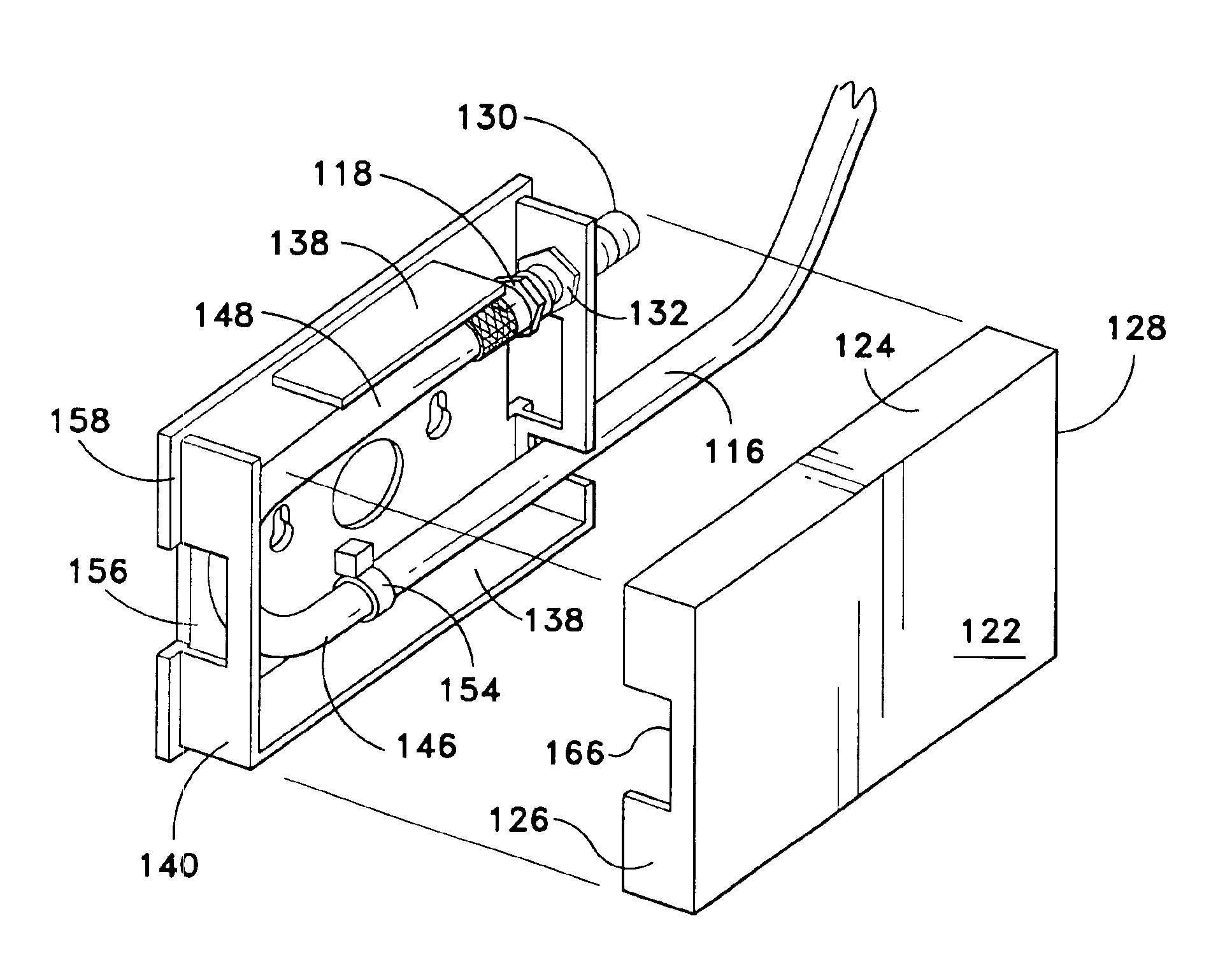
[0030]The present invention is a surface mount cable jack comprising a base, a cover, a plurality of access ports, and a retention means.

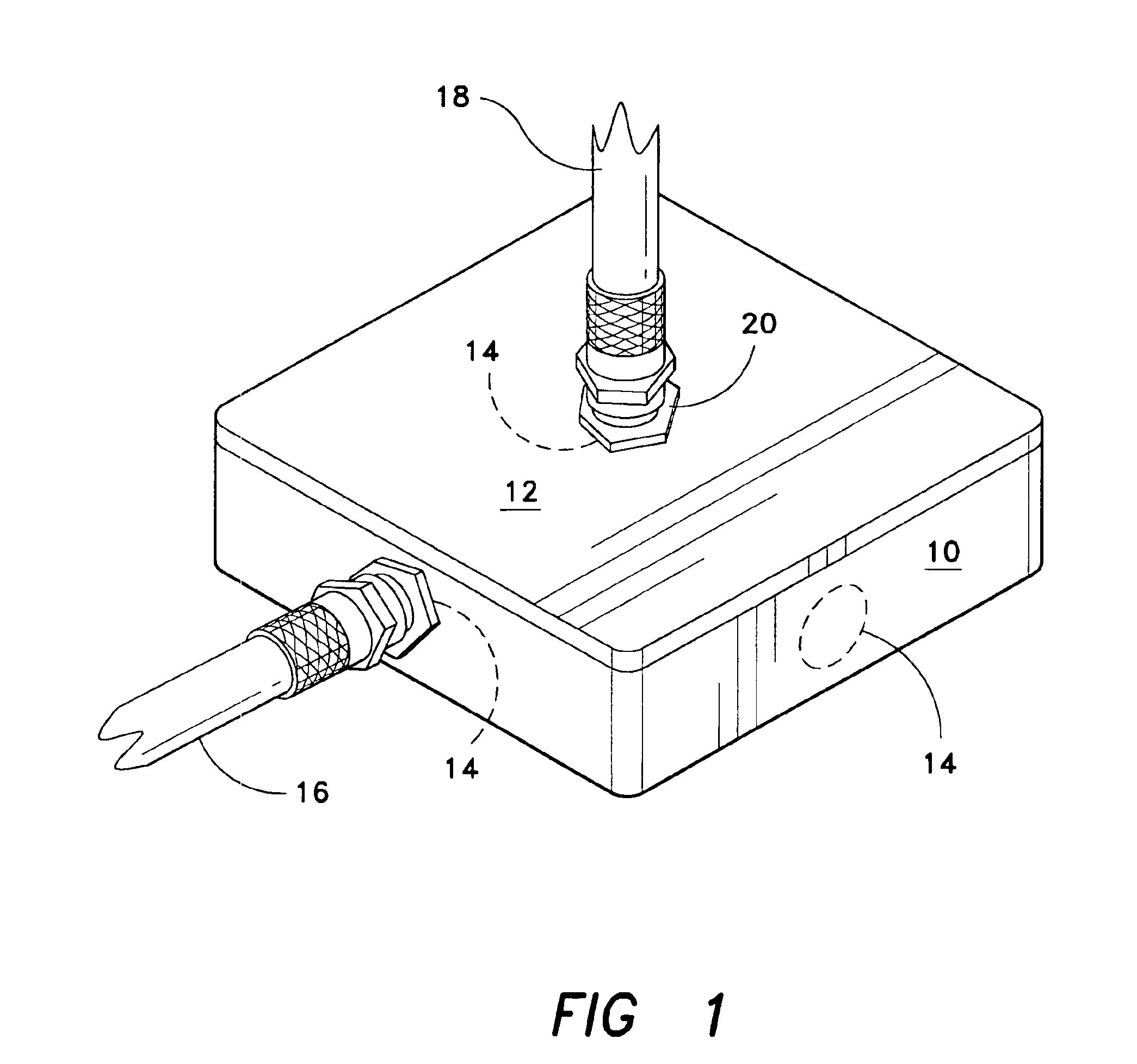
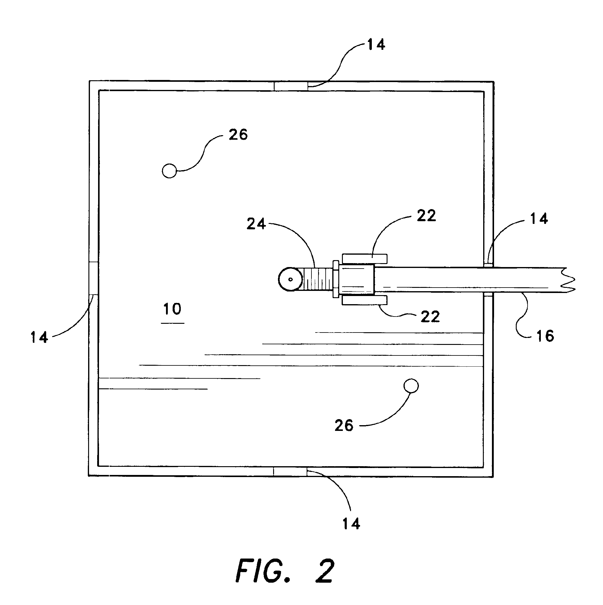
[0031]Referring to the Figures, an environmental, perspective view of a surface mount cable jack according to the present invention in FIG. 1. The base 10 is hollow and, together with the cover 12, forms the jack housing. The base 10 provides an open-topped cable enclosure formed by a bottom wall and a sidewall extending around the bottom wall and including retention means for securing cables and their various connecting components. The sidewall is at least high enough to enclose a cable and a plurality of connectors. The retention means may be a plurality of clamps or a receptacle into which cables or connectors may be snapped, clamped, screwed or otherwise fastened to secure cables and cable splitters or connectors. The retention means may be a plurality of flexible pins protruding from the bottom wall of the base 10 perpendicular to the bottom w...


PUM


Abstract

The cable television (CATV) jack is a surface mount jack and provides an aesthetically pleasing device for routing communications cables. An extra length of cable may be stored inside the jack, and there are multiple ports on the surfaces of the jack to provide several options for cable connections. The jack has at least one port for entry of an input cable and at least one double female connector extending out from an extension port in the jack for securing an output cable. The jack securely retains the cable and connectors to prevent broken connections. The jack is easily mounted to a surface using screws, or other means, such as adhesive.

Description

CROSS-REFERENCE TO RELATED APPLICATION[0001]This application claims the benefit of U.S. Provisional Patent Application Ser. No. 60 / 399,451, filed Jul. 31, 2002.FIELD OF THE INVENTION[0002]The present invention relates generally to connectors for communications cables, and more particularly to a surface mount cable television (CATV) jack.DESCRIPTION OF RELATED ART[0003]Cable connectors for coaxial and fiber-optic cable are well known. The connectors are used to terminate the end of run of cable, either for direct connection to a television or piece of equipment, or for connection to a second run of cable via an adapter, for purposes such as CATV and other audio, video and data transmissions. The coaxial or fiber-optic cables are typically terminated at places convenient for locating a flush-mounted jack, or convenient for access to the equipment that uses the cables. However, the aesthetics and usefulness of available cable termination methods varies greatly.[0004]Cables are often ro...

Claims


Application Information

Patent Timeline
Patent Type & Authority Patents(United States)
IPC IPC(8): H01R13/72H01R13/00H01R13/73
CPCH01R13/73H01R13/72
Inventor CULBERTSON, GEORGE A.
Owner CULBERTSON GEORGE A
Why Eureka
Try Eureka