Drive method of light-emitting display panel and organic EL display device

a technology of light-emitting display panel and drive method, which is applied in the direction of static indicating device, solid-state device, instruments, etc., can solve the problems of panel driven and lit with a certain degree of light emission luminance, deteriorating of el elements,

Inactive Publication Date: 2005-05-17
TOHOKU PIONEER CORP
View PDF5 Cites 23 Cited by
  • Summary
  • Abstract
  • Description
  • Claims
  • Application Information

AI Technical Summary

Benefits of technology

[0043]In this case, the reverse bias voltage for precharging the parasitic capacitances of the light-emitting elements may be obtained by dividing the voltage output from the drive voltage source based on a degree of control of the

Problems solved by technology

However, the constant current circuit shown in FIG. 3 is ordinarily used because of the reasons that the voltage/luminance characteristics of the EL elements are unstable to a temperature change while the current/luminance characteristics thereof are stable to the temperature change and that there is a possibility that the EL elements are deteriorated by an excessive current, and the

Method used


Image

  • Drive method of light-emitting display panel and organic EL display device
  • Drive method of light-emitting display panel and organic EL display device
  • Drive method of light-emitting display panel and organic EL display device

Examples


first embodiment

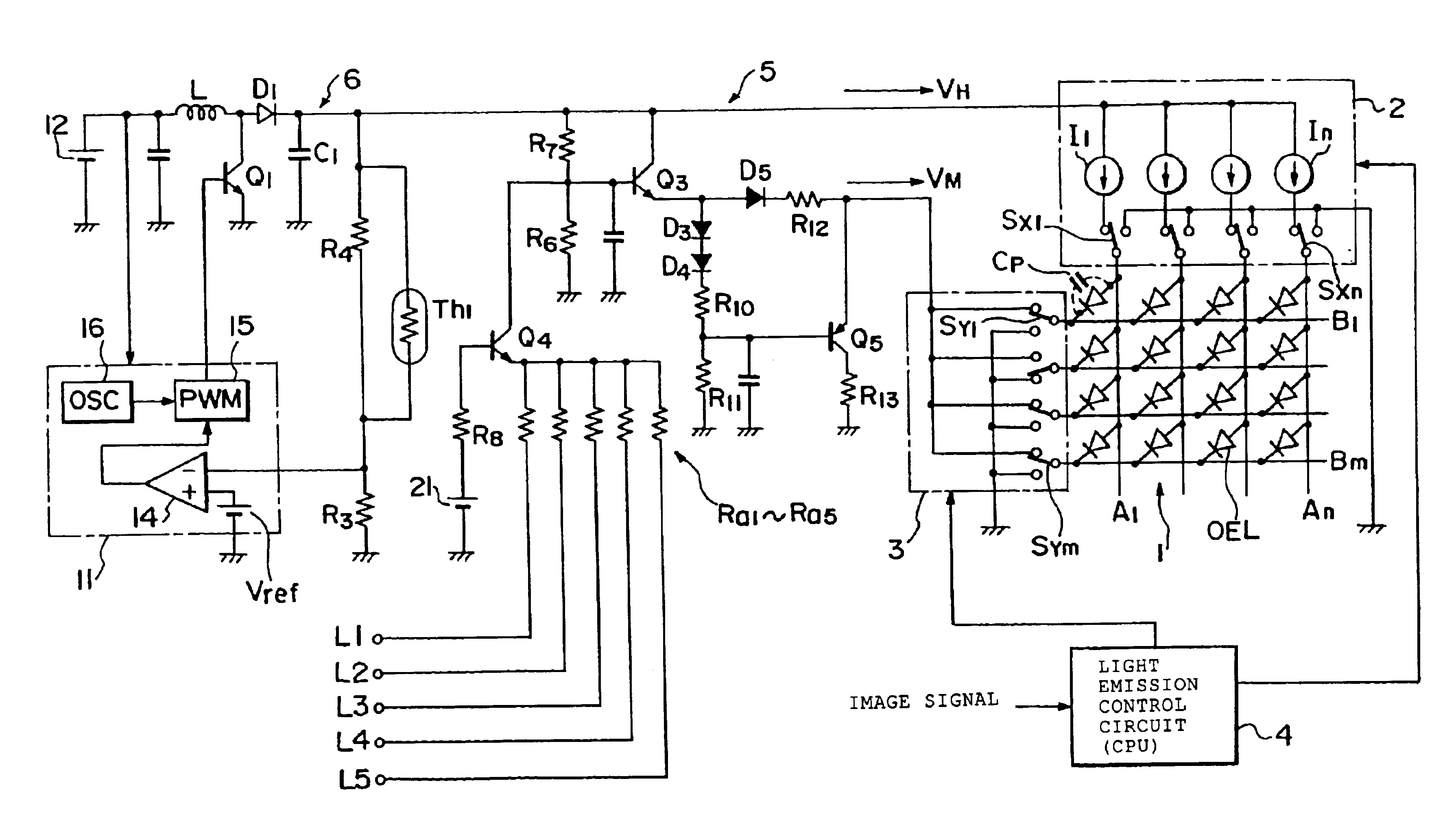
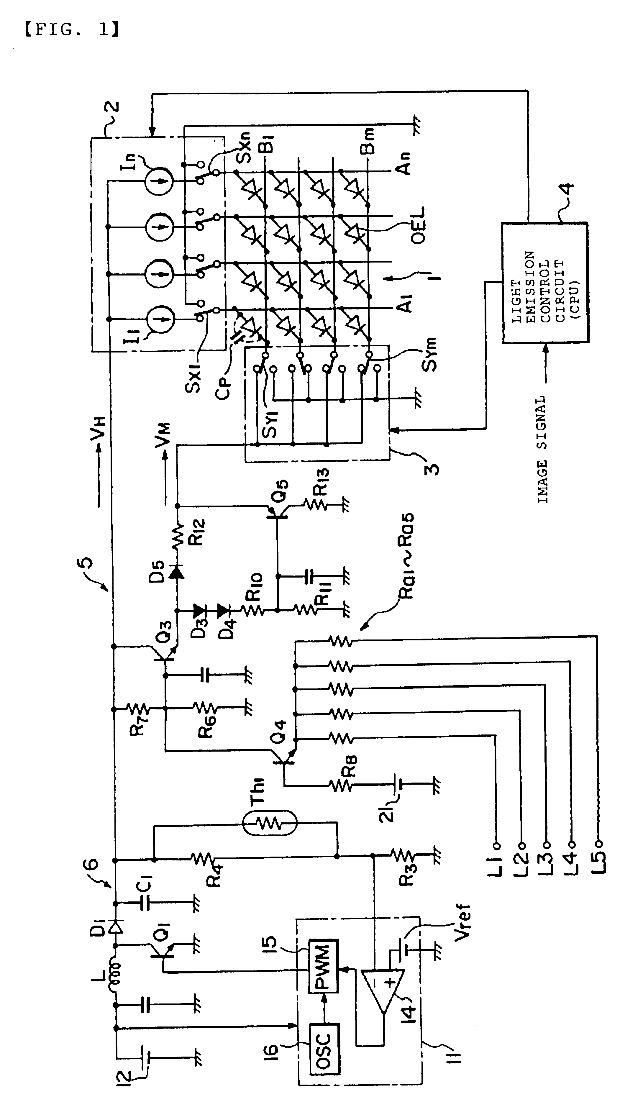
[0053]A preferable embodiment of a display device employing a drive method according to the present invention will be explained with reference to the drawings. FIG. 1 shows a drive circuit to which the present invention is applied and a display panel whose light emission is controlled by the drive circuit. Note that, in FIG. 1, a display panel 1, an anode line drive circuit 2, a cathode line scan drive circuit 3, and a light emission control circuit 4 that drive the display panel 1 have the same functions as those of the respective circuits shown in FIG. 3 described above, and thus the detailed description thereof is appropriately omitted.

[0054]In the first embodiment shown in FIG. 1, a DC-DC converter is used as a drive voltage source 6. Note that while the DC-DC converter described below creates a direct current output (output voltage=VH) by PWM (pulse width modulation) control, it may utilize PFM (pulse frequency modulation) control.

[0055]The DC-DC converter is arranged such that...

second embodiment

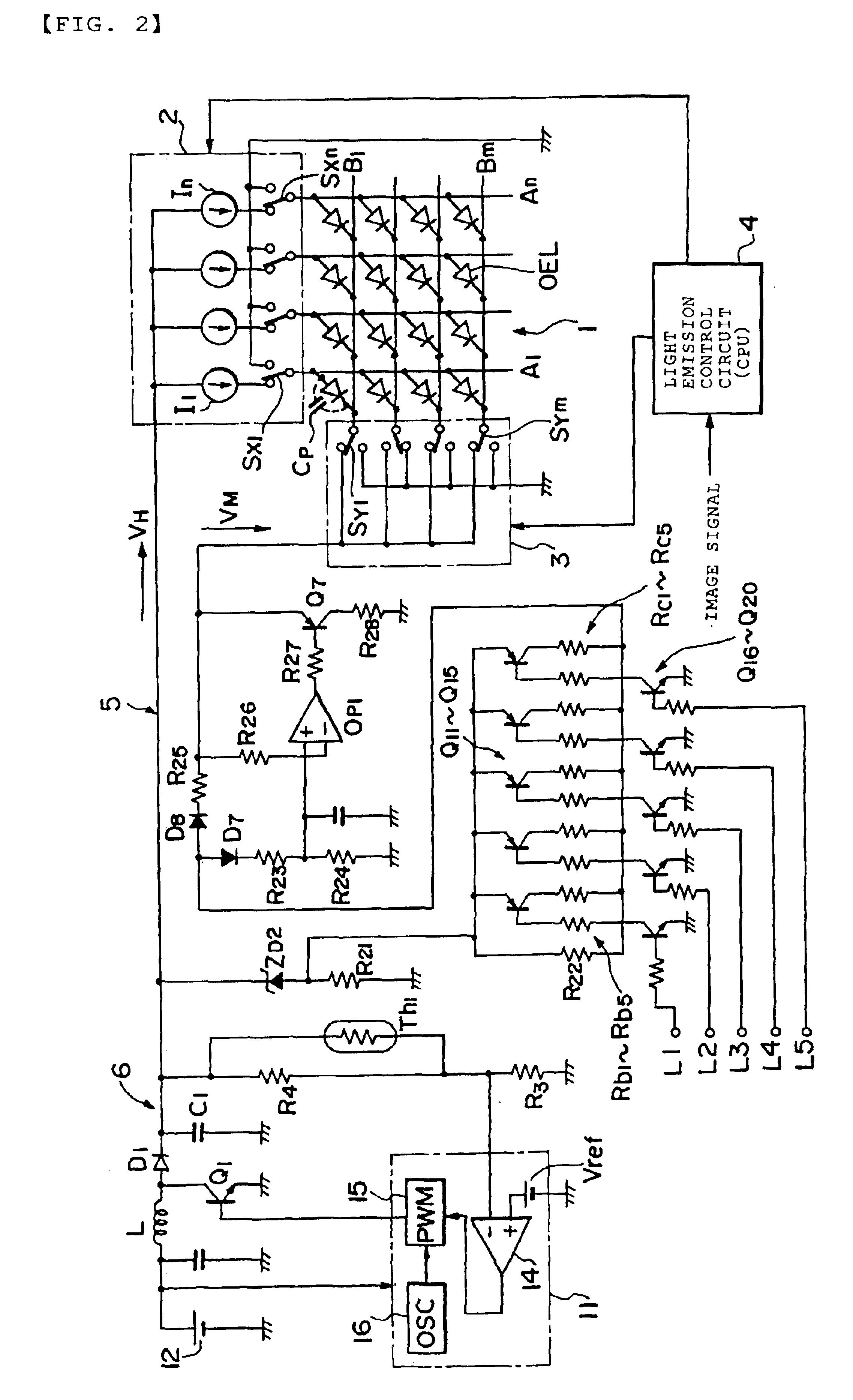
[0068]Next, FIG. 2 shows the drive circuit to which the present invention is applied. Note that, in FIG. 2, a display panel 1, an anode line drive circuit 2, a cathode line scan circuit 3, and a light emission control circuit 4 for driving the display panel as well as a drive voltage source 6 composed of DC-DC converter have the same functions as those of the respective circuits shown in FIG. 1 described above, and thus the detailed description thereof is appropriately omitted.

[0069]In the drive circuit shown in FIG. 2, a reverse bias voltage creation circuit 5 creates the reverse bias voltage VM making use of the output voltage VH obtained by the DC-DC converter similarly to the first embodiment. The reverse bias voltage VM is used as a charge voltage source for precharging the parasitic capacitances Cp of organic EL elements by simultaneously using the cathode reset method described above with reference to FIG. 6 also in the second embodiment.

[0070]As shown in FIG. 2, the reverse ...


PUM


Abstract

In a drive method of a light-emitting display panel capable of emitting light in low luminance, the parasitic capacitances of the light-emitting elements disposed in the light-emitting display panel are precharged making use of a reverse bias voltage before they are lit. In this case, a reverse bias voltage created by a reverse bias voltage creation circuit or a peak current being precharged is controlled by selectively grounding control terminals based on dimmer control. In particular, when the light-emitting elements are emitted in low luminance, the reverse bias voltage is output in a low level, thereby the light-emitting elements are prevented from being precharged with an excessive voltage. The above arrangement can realize light emission control in low luminance.

Description

BACKGROUND OF THE INVENTION[0001]1. Field of the Invention[0002]The present invention relates to a drive method of a light-emitting display panel using, for example, organic electroluminescence (EL) elements as light-emitting elements and to a display device using the light-emitting display panel, and more particularly, to a control technology for controlling the luminance of the light-emitting display panel when it is lit.[0003]2. Description of the Related Art[0004]Attention is given to an organic EL display unit as a display unit replacing a liquid crystal display unit because the organic EL display unit can reduce power consumption, can display an image of high quality and further can be reduced in thickness. This is because the efficiency and life of the organic EL display unit have been improved to a practically usable level by using an organic compound promising good light emitting characteristics for the light-emitting layers of EL elements used in the EL display unit.[0005]...

Claims


Application Information

Patent Timeline
IPC IPC(8): G09G3/32H01L51/50G09G3/20G09G3/30
CPCG09G3/3216G09G3/3266G09G2310/0251G09G2310/0256G09G2330/028G09G2320/0606G09G2320/0626G09G2330/02G09G2320/0209
Inventor TOGASHI, MASATOFUJITA, DAISUKEHENMI, KOJIYAZAWA, NAOKISUZUKI, GENMORIYA, KEISUKE
Owner TOHOKU PIONEER CORP
Why Eureka
Try Eureka