
Efficient coupler detector circuit with reduced harmonic distortion

Active Publication Date: 2005-05-17
SKYWORKS SOLUTIONS INC
View PDF7 Cites 4 Cited by
  • Summary
  • Abstract
  • Description
  • Claims
  • Application Information

AI Technical Summary

Benefits of technology

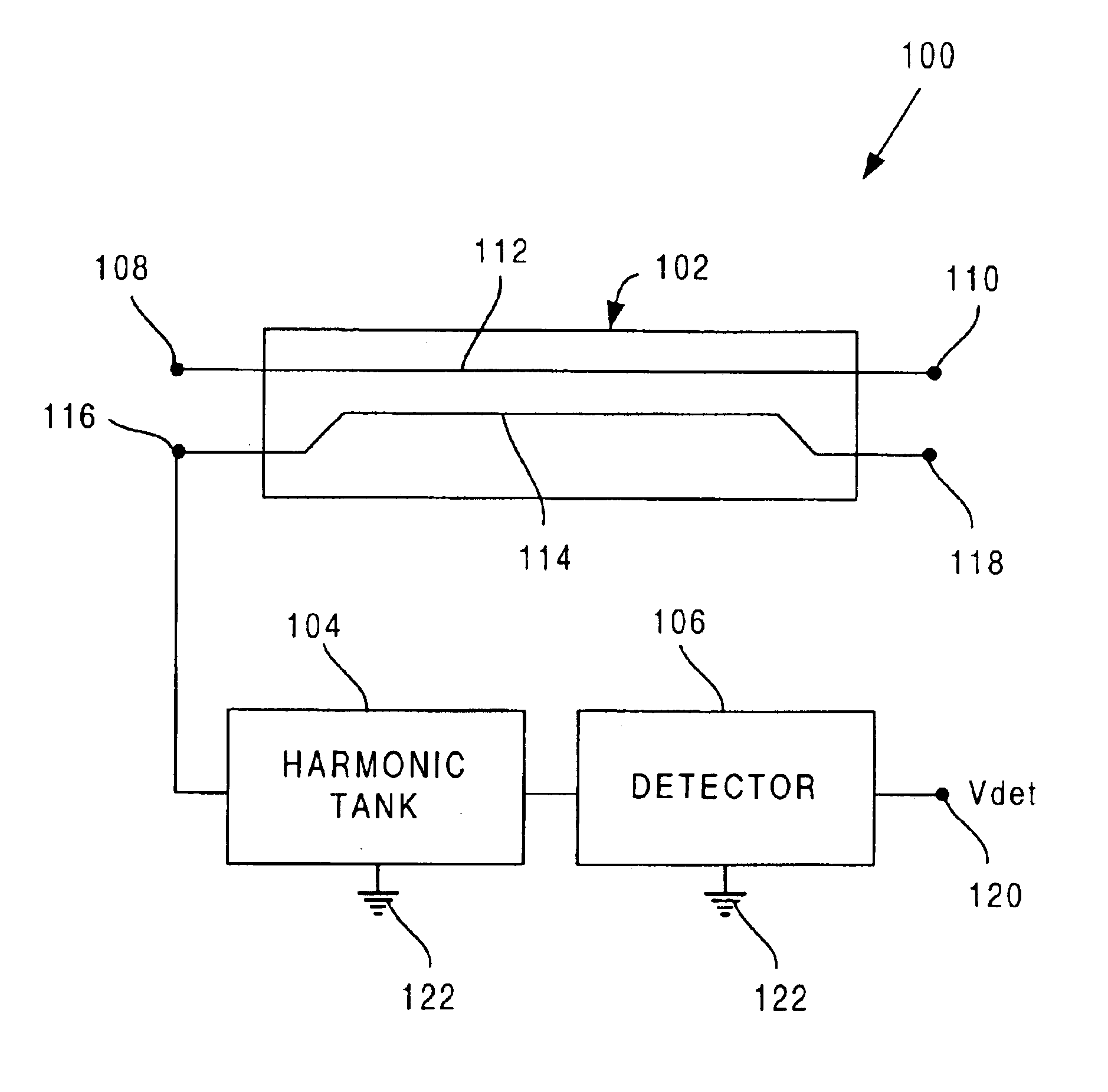
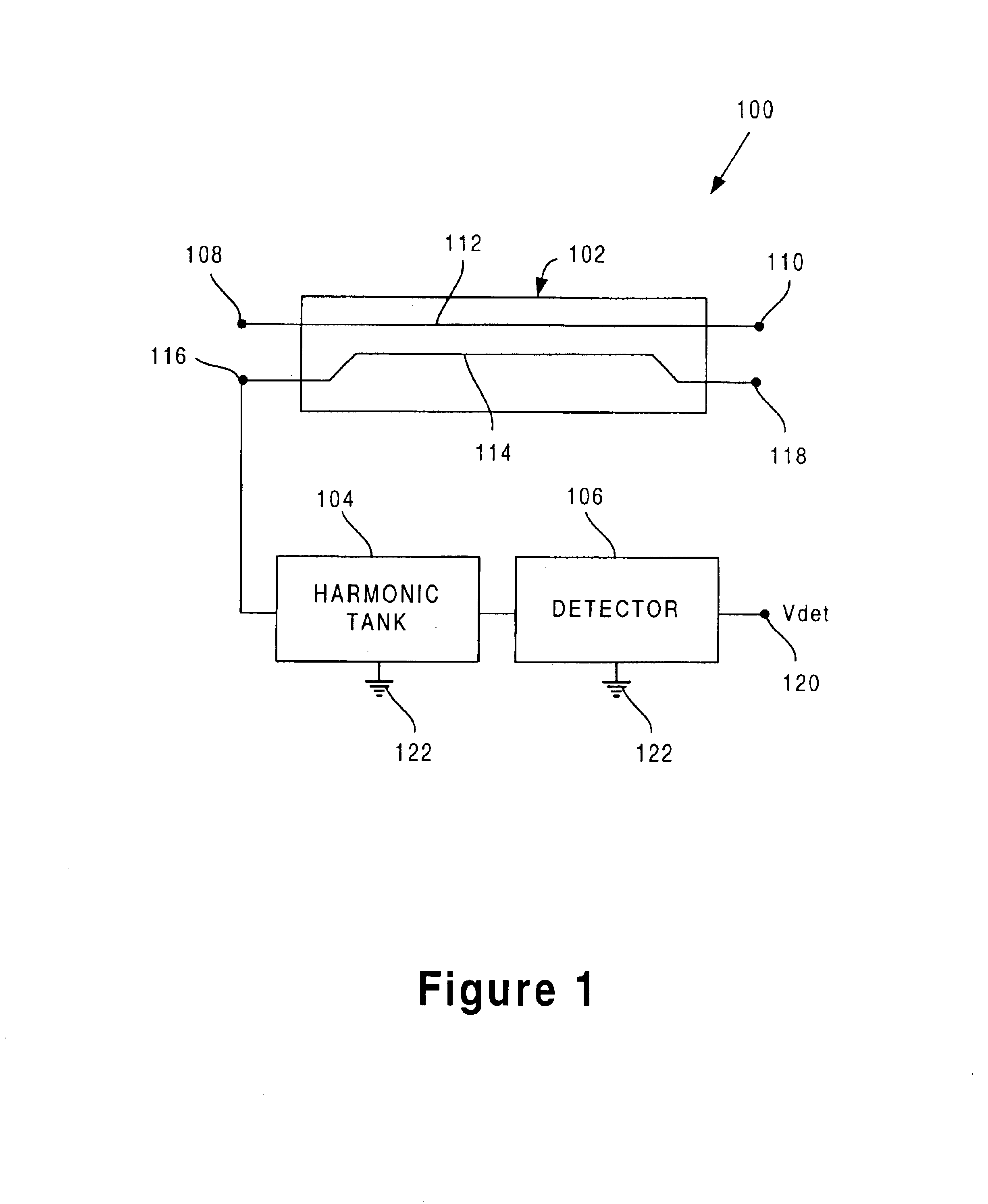
[0008]The present invention is directed to an efficient coupler detector circuit with reduced harmonic distortion. The invention overcomes the need in the art for a coupler detector circuit which does not reduce the efficiency of the power amplifier.
[0013]According to various embodiments of the invention, harmonic distortion is significantly reduced along the signal path of the transmission line without adding loss to the transmission line. As a result, reduced harmonic distortion along the signal path of the transmission line is achieved in a significantly efficient manner. Other features and advantages of the present invention will become more readily apparent to those of ordinary skill in the art after reviewing the following detailed description and accompanying drawings.

Problems solved by technology

A known problem with the coupler detector approach, however, is that harmonic signals can be generated by the detector circuit.
These harmonic signals can be re-coupled onto the transmission line and introduce undesirable harmonic distortion into the transmission line, severely degrading the signal transmitted along the transmission line.
However, the filter also adds loss to the signal path or “through path” along the transmission line.
As a consequence, the efficiency of the power amplifier is significantly degraded, which is undesirable.
There is also a need in the art for a coupler detector circuit which does not reduce the efficiency of the power amplifier.

Method used


Image

  • Efficient coupler detector circuit with reduced harmonic distortion
  • Efficient coupler detector circuit with reduced harmonic distortion
  • Efficient coupler detector circuit with reduced harmonic distortion

Examples


Embodiment Construction

[0016]The present invention is directed to an efficient coupler detector circuit with reduced harmonic distortion. The following description contains specific information pertaining to the implementation of the present invention. One skilled in the art will recognize that the present invention may be implemented in a manner different from that specifically discussed in the present application. Moreover, some of the specific details of the invention are not discussed in order to not obscure the invention. The specific details not described in the present application are within the knowledge of a person of ordinary skill in the art.

[0017]The drawings in the present application and their accompanying detailed description are directed to merely exemplary embodiments of the invention. To maintain brevity, other embodiments of the invention which use the principles of the present invention are not specifically described in the present application and are not specifically illustrated by th...


PUM


Abstract

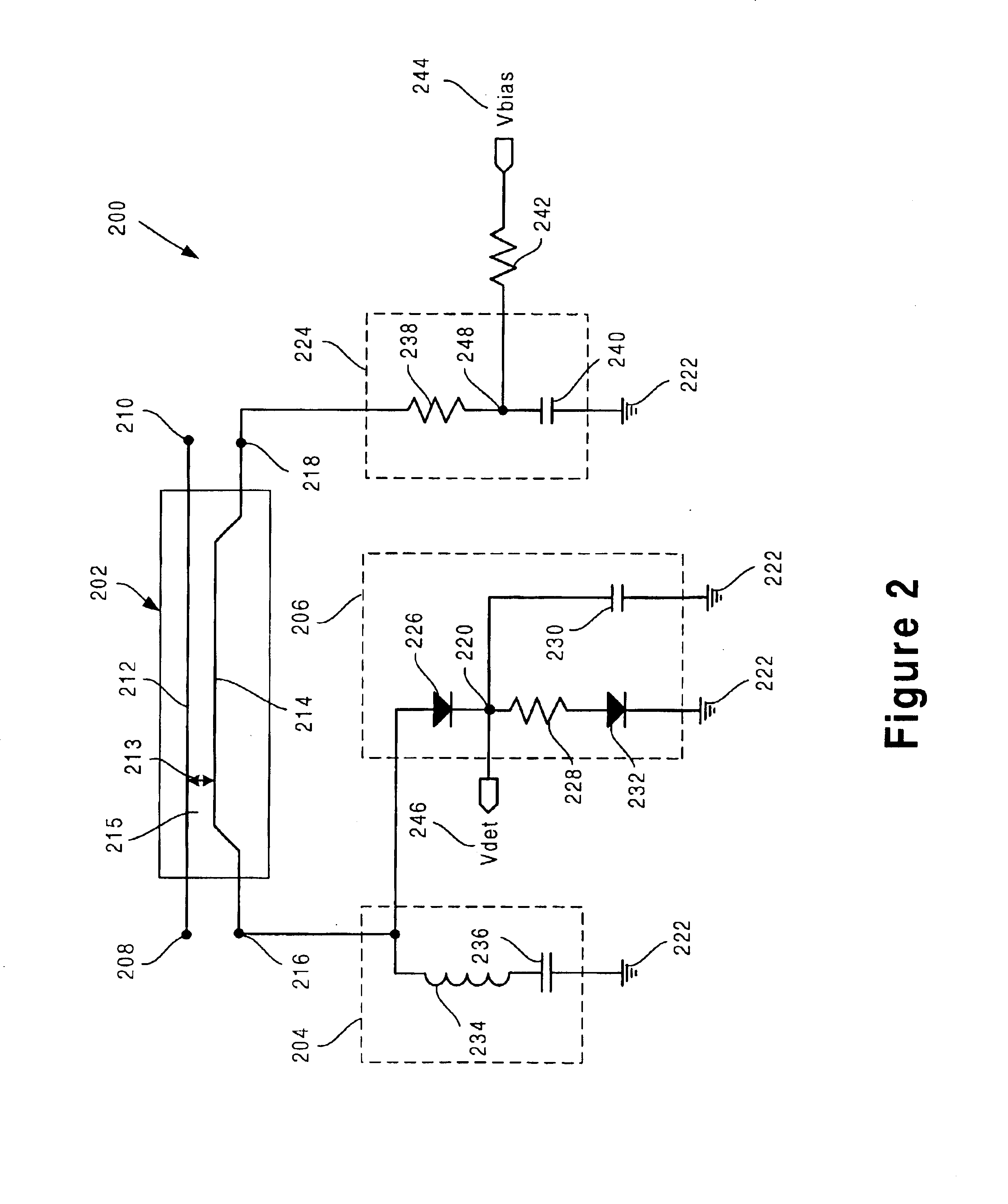
An exemplary coupler detector circuit comprises a coupler, a detector circuit, and a harmonic tank. The coupler has a transmission line electromagnetically coupled to a coupled line, and the coupled line has an isolated node and a coupled node. The transmission line may, for example, be a 50 ohm RF line for transmitting RF energy. The detector circuit is connected to the coupled node and is configured to detect a power transmitted along the transmission line. The harmonic tank is connected to the coupled node, and is configured to short to ground at least one harmonic signal transmitted along the coupled node.

Description

BACKGROUND OF THE INVENTION[0001]1. Field of the Invention[0002]The present invention is generally in the field of power amplifiers. More specifically, the invention is in the field of power amplifier power detection.[0003]2. Related Art[0004]Various methods for detection the power output of a power amplifier are known. For example, in the coupler detector approach, a coupled line is electromagnetically coupled to a transmission line, and a detector circuit is connected to one node of the coupled line to detect the power output transmitted by a power amplifier along the transmission line.[0005]A known problem with the coupler detector approach, however, is that harmonic signals can be generated by the detector circuit. These harmonic signals can be re-coupled onto the transmission line and introduce undesirable harmonic distortion into the transmission line, severely degrading the signal transmitted along the transmission line.[0006]The conventional approach to reducing harmonic dis...

Claims


Application Information

Patent Timeline
IPC IPC(8): G01R21/00G01R21/01G01R21/12H01P5/18
CPCG01R21/01H03G3/3042H01P5/182G01R21/12
Inventor WYSE, RUSSELLCEBI, HAKISHIE, TERRY J.
Owner SKYWORKS SOLUTIONS INC
Learn More