Crane safety devices and methods

a safety device and crane technology, applied in the field of crane safety devices and devices, can solve the problems of not being widely used, the beam is often obscured by the load, and the safety devices mounted proximally to the moving crane parts have not been widely used, so as to facilitate communication, minimize background noise, and increase the safety of workers.

Inactive Publication Date: 2005-05-17
SHAW JACK B
View PDF64 Cites 57 Cited by
  • Summary
  • Abstract
  • Description
  • Claims
  • Application Information

AI Technical Summary

Benefits of technology

[0011]In still further aspects of the invention, a microphone and speaker system is included in the crane warning device such that the operator can communicate with the workers. For example, some embodiments of the invention may provide a two-way communication device that allows a crane's operator and a workman working on the ground to converse regarding the operation of the crane. Worker safety is vastly increased because the worker may use both hands to manipulate the load while verbally signaling the operator. Accordingly, the controls for the communication system may be “hands free” controls, allowing the crane operator and/or the workmen to communicate without having to manipulate the communication system. Still further, the communication system may employ noise canceling or noise reduction technology to minimize background noise, such as noise from the crane's engine. According to various embodiments of the invention, the communication system may be wireless. For example, the communication system may employ low electromagnetic frequencies that can penetrate building and rock. Alternately, various embodiments of the invention may locate the antenna for the crane operator's communication terminal at the end of the crane's boom, to facilitate communication with a communication terminal carried by one or more workmen. In still further aspects of the invention, the crane warning devices with communication devices are mounted on different sides of the crane so that the operator has immediate communications with all sides of the crane, further enhancing safety.
[0012]In further aspects of the invention, a camera may be mounted such that a “birds eye” view of the load and/or suspended device may be obtained by the operator sitting in the cab from a remotely mounted camera. The bird's eye view, alone or in conjunction with the audio communications, vastly increases safety and efficiency of the crane operating environment. With various embodiments of the invention, two or more cameras may be placed at different locations on the crane, such as along the j

Problems solved by technology

Further, if there is a warning beacon on the safety device, then the beacon often becomes obscured by the load, especially where the load is large or of an unusual shape.
This condition is dangerous bec

Method used


Image

  • Crane safety devices and methods
  • Crane safety devices and methods
  • Crane safety devices and methods

Examples


Embodiment Construction

Crane Warning Devices

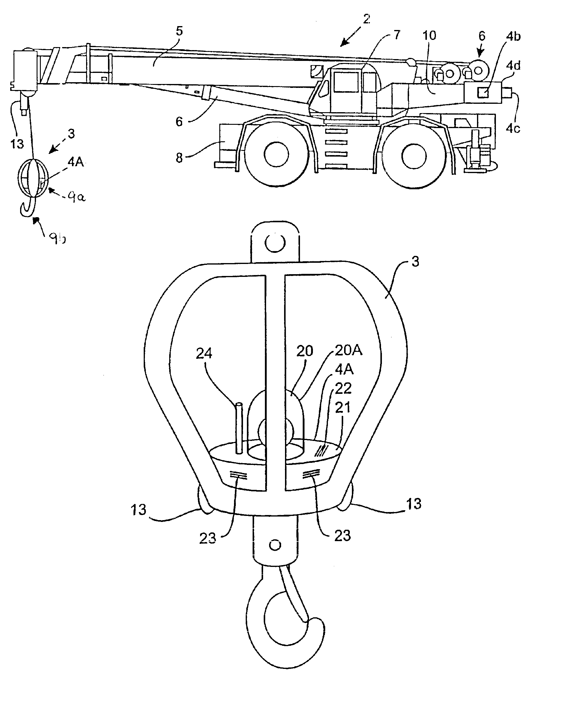
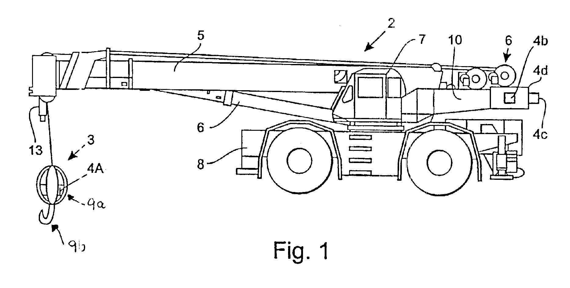
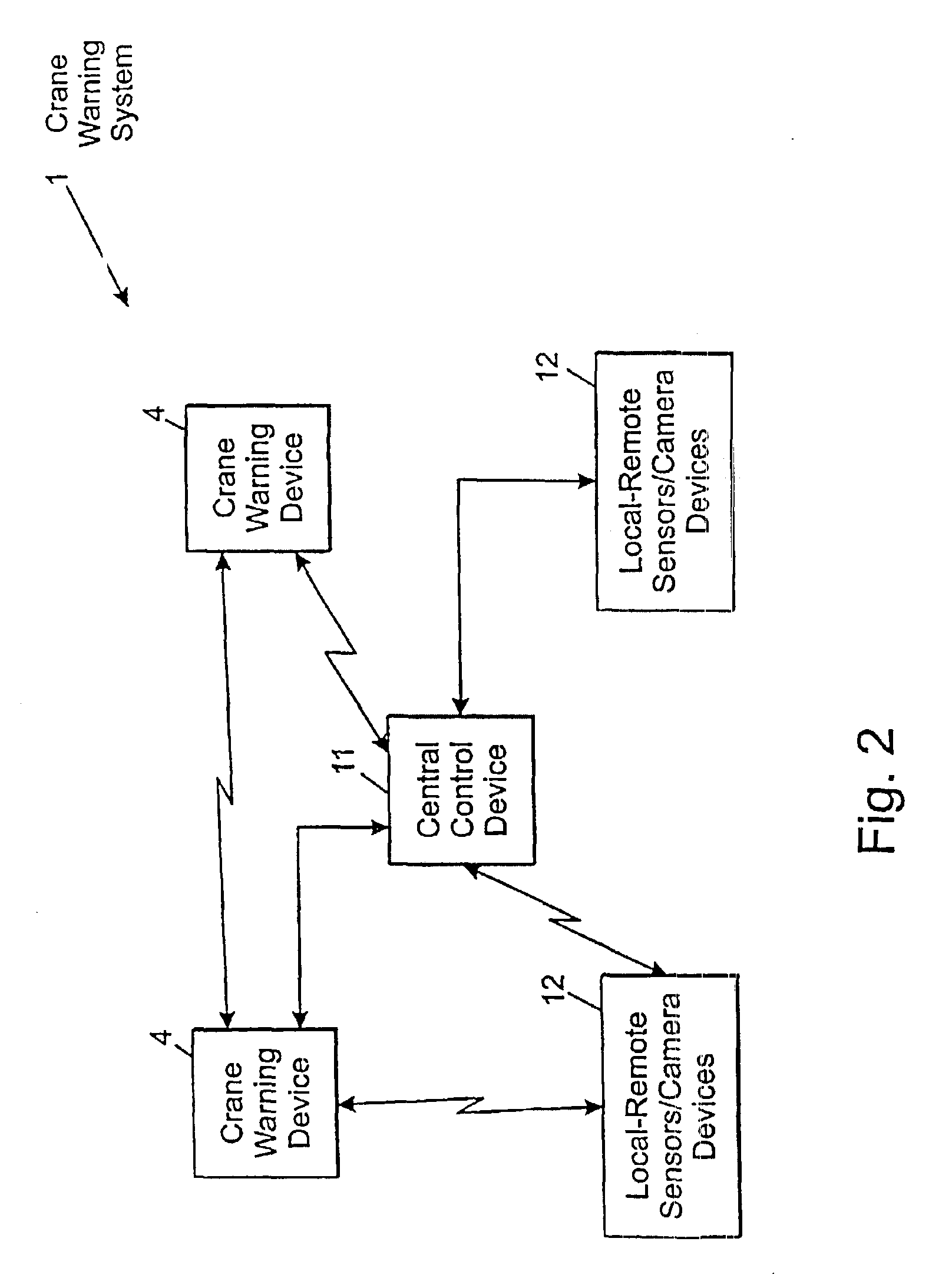
[0027]Referring to FIGS. 1 and 2, a crane warning system is incorporated in a crane 2 to improve the safety of workers (not shown) in the vicinity of the crane. The crane 2 typically includes a boom 5, various movement mechanisms 6 to move the boom 5, carriage (not shown in the embodiment of FIG. 1), and a device 3 suspended from the boom 5 in any one of a plurality of direction. In the illustrated embodiment, the suspended device 3 is a ball 9a with a hook 9b. With alternate embodiments of the invention, however, the suspended device 3 may be a single hook, a block (e.g., as part of a block and tackle combination), a personnel basket, an electromagnet, a wrecking ball, or any other device that may be suspended from a crane's boom for a desired crane configuration. As will be appreciated by those of ordinary skill in the art, multiple devices 3 may be suspended from a crane 2. For example, a particular crane configuration may have both a ball and a personnel bas...


PUM


Abstract

An improved crane warning system that includes acceleration sensors, motion sensors, hydraulic sensors, remote communications and/or a camera. The crane warning system may include a crane warning device integrated into the device suspended from the crane.

Description

[0001]This application is a continuation-in-part application of U.S. patent application Ser. No. 09 / 383,192, entitled “Crane Safety Devices And Methods” filed Aug. 26, 1999, now U.S. Pat. No. 6,549,139, which in turn is a continuation application of International Application No. PCT / US98 / 03482, entitled “Crane Safety Devices And Methods,” filed Feb. 26, 1998, which in turn was a continuation-in-part application of U.S. patent application Ser. No. 09 / 030,249, filed on Feb. 25, 1998, now U.S. Pat. No. 6,140,930 (and which issued on Oct. 31, 2000 as U.S. Patent and Trademark Office) which in turn was based on U.S. Provisional Patent Application No. 60 / 039,825 entitled “Crane Safety Devices And Methods,” filed Feb. 27, 1997, now abandoned, each of which applications are hereby expressly incorporated herein by reference in their entireties. In addition, copending U.S. patent application Ser. No. 09 / 447,812, entitled “Crane Safety Devices And Methods” filed Nov. 23, 1999, is hereby expres...

Claims


Application Information

Patent Timeline
IPC IPC(8): B66C13/18B66C13/44B66C15/04B66C15/00B66C15/06B66C13/46
CPCB66C13/44B66C15/06B66C15/04B66C13/46B66C13/54
Inventor SHAW, JACK B.
Owner SHAW JACK B
Why Eureka
Try Eureka