
Method and apparatus for controlling electronically commutated motor operating characteristics

a technology of electronic commutation and operating characteristics, which is applied in the direction of electronic commutator, motor/generator/converter stopper, dynamo-electric converter control, etc., can solve the problems of requiring time-consuming changes of control circuits or motor internals, ecm configuration problems may be further complicated, and the ecm is difficult to remove from one system for installation in another system

Inactive Publication Date: 2005-05-17
REGAL BELOIT AMERICA
View PDF18 Cites 633 Cited by
  • Summary
  • Abstract
  • Description
  • Claims
  • Application Information

AI Technical Summary

Benefits of technology

[0004]In one aspect, a method is provided for selecting operating characteristics of a permanent magnet DC brushless motor using a control module. The method includes coupling an electronic commutator to the permanent magnet DC brushless motor, electrically coupling at least one control module to the commutator and selecting operating characteristics for the motor through the control module, the control modules are configured for controlling operating characteristics of the electronically commutated permanent magnet DC brushless motor.
[0005]In another aspect, a control assembly for an electronically commutated motor is provided that includes a permanent magnet DC brushless motor, an electronic commutator comprising an H-bridge inverter circuit, rotor

Problems solved by technology

Because of the complexity of the many possible desired operating characteristics, it may be difficult to remove an ECM from one system for installation in another system.
The ECM configuration problem may be further complicated when motor manufacturers produce a base motor and then develop a product line of motors with different operating characteristics based upon the base motor.
Changing motor characteristics, such as, variable speed, for example, may require time-consuming changes of the control circuit or motor internals.
Designing, manufacturing, and stocking different parts is more expensive than designing, manufacturing, and stocking one standardized part which can be programmed for many different applications or coupled with different modules to satisfy the needs of different applications.

Method used


Image

  • Method and apparatus for controlling electronically commutated motor operating characteristics
  • Method and apparatus for controlling electronically commutated motor operating characteristics
  • Method and apparatus for controlling electronically commutated motor operating characteristics

Examples


Embodiment Construction

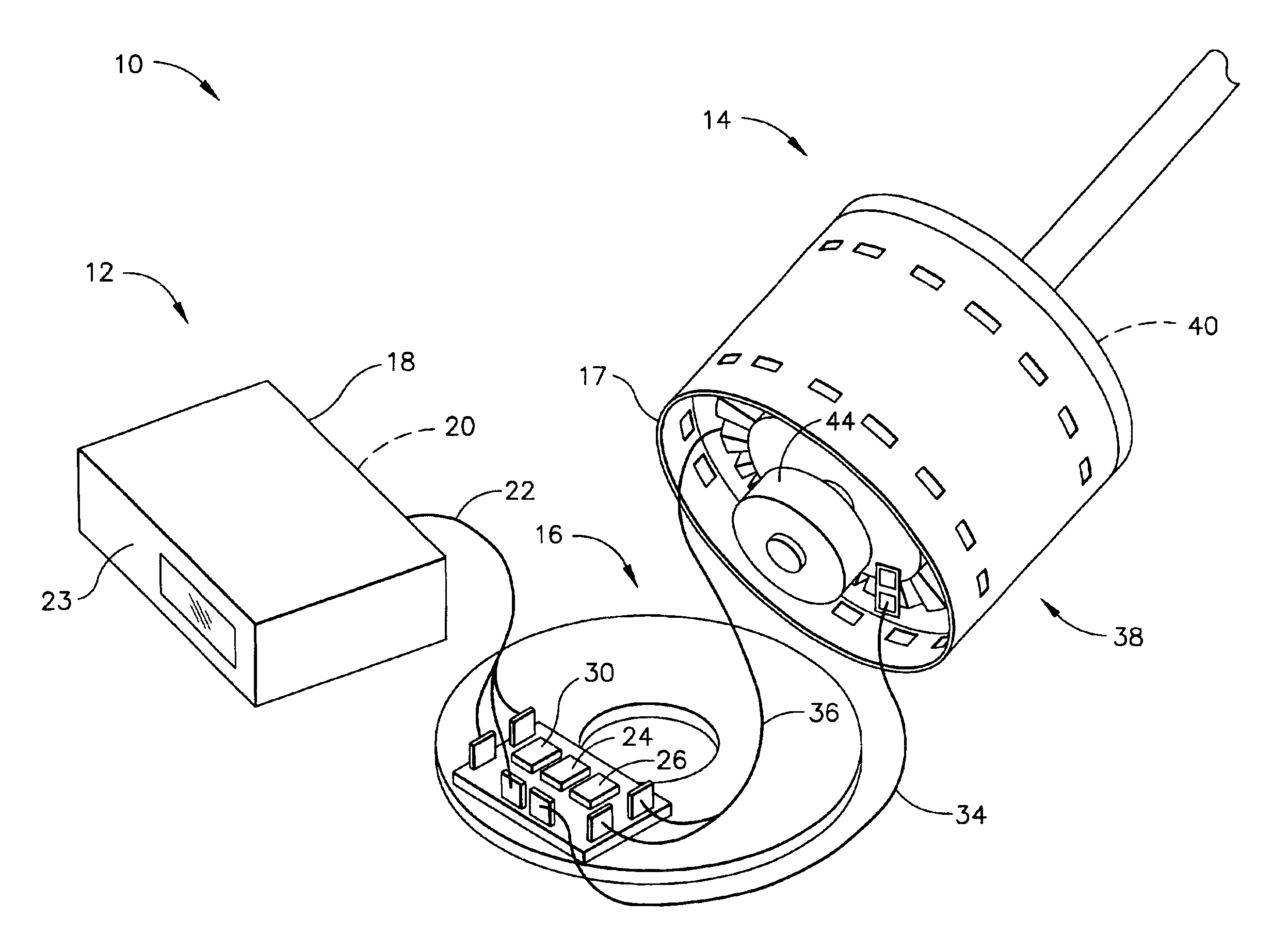
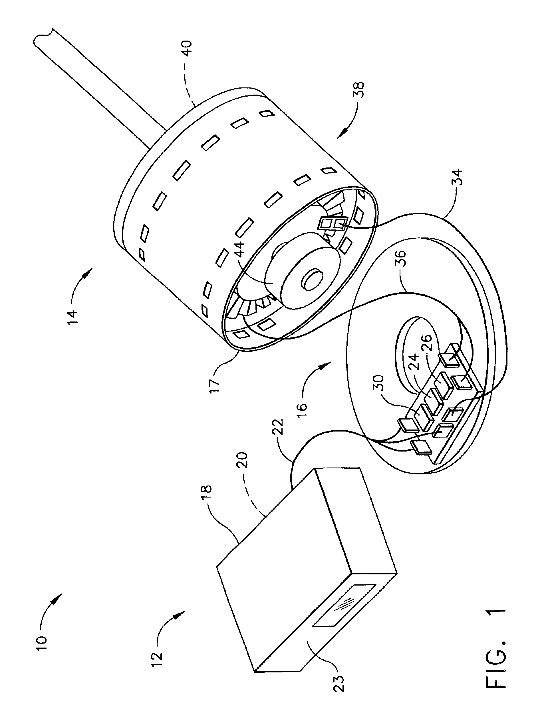
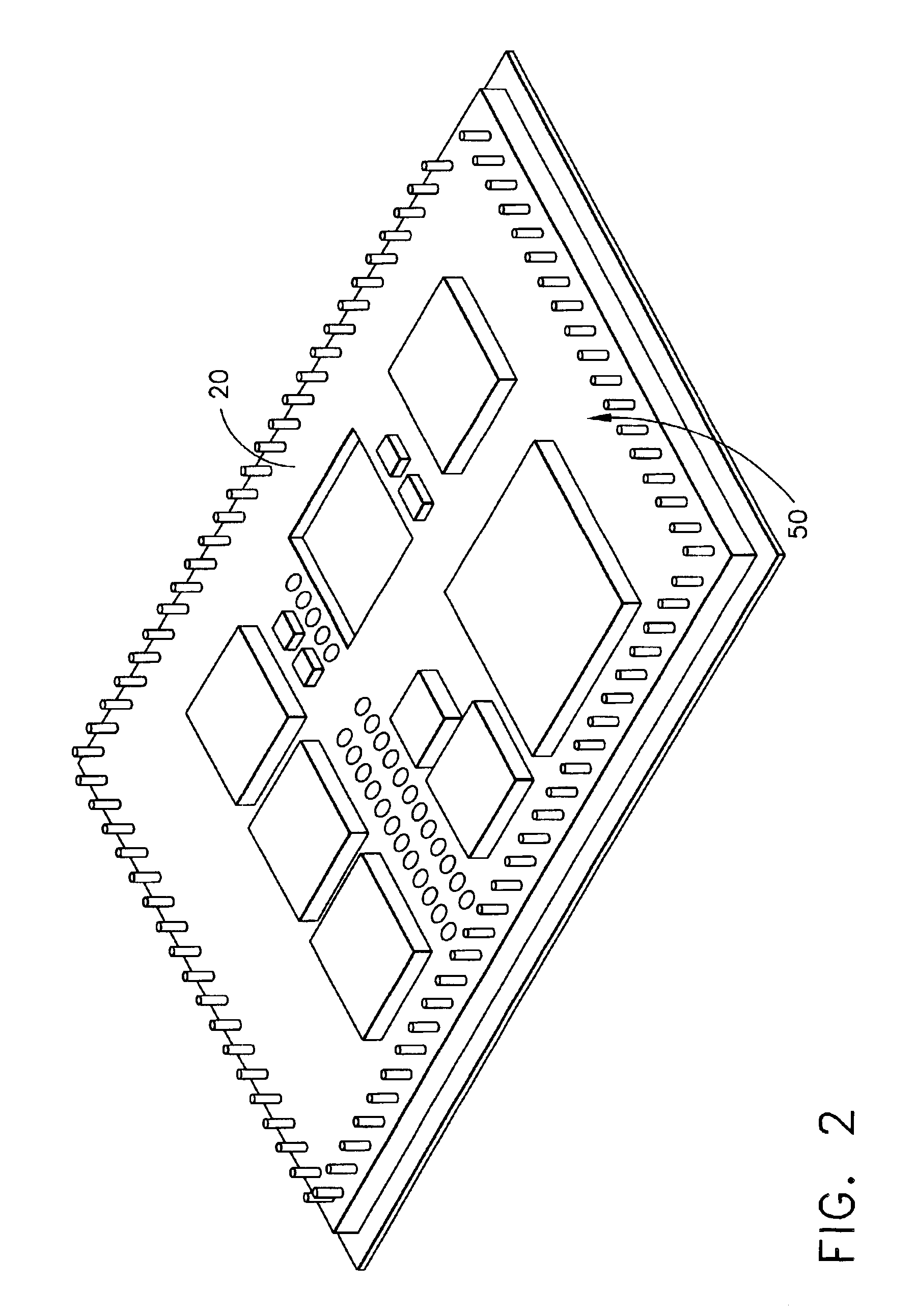
[0012]FIG. 1 is a block diagram of an electrically commutated motor (ECM) control assembly 10 including a control module 12, a permanent magnet DC brush-less motor 14 and a commutator 16. When fully assembled, commutator 16 is mechanically coupled to a motor end shield 17 to form an electronically commutated motor. Control module 12 includes an enclosure 18 and a printed circuit board 20 (not shown). In one embodiment, printed circuit board 20 includes a microprocessor configured to control the output of the printed circuit board to control the operating characteristics of motor 14. In another embodiment, printed circuit board 20 is populated with a plurality of electronic components (not shown) coupled to printed circuit board 20 and each other to control the output of the printed circuit board 20 to control the operating characteristics of motor 14. In an exemplary embodiment, printed circuit board 20 is potted in enclosure 18. In one embodiment, the potting compound is UR-330, pa...


PUM


Abstract

A permanent magnet DC brushless motor control assembly permits a user to select the permanent magnet DC brushless motor operating characteristics by selecting appropriate control circuits to interface with the motor. The assembly includes a permanent magnet DC brushless motor, a commutator electrically coupled to the motor, and at least one control module electrically coupled to the commutator, to control operating characteristics of the permanent magnet DC brushless motor.

Description

BACKGROUND OF THE INVENTION[0001]This invention relates to electrically commutated motors, and more particularly, to methods and approaches used to control the operating characteristics of an electrically commutated motor.[0002]Electrically commutated motors (ECMs) are used in a wide variety of systems operating in a wide variety of industries. As such, the ECMs are subject to many operating conditions and often, the operating conditions necessitate that the operating characteristics of the ECM be changed to match the requirements of the associated application (i.e. different speeds or airflow requirements for heating, cooling, and constant fan for residential HVAC applications). Because of the complexity of the many possible desired operating characteristics, it may be difficult to remove an ECM from one system for installation in another system. More specifically, the ECM control circuits and interfaces must typically be changed to enable the ECM to be used with different operatin...

Claims


Application Information

Patent Timeline
IPC IPC(8): H02P6/00
CPCH02P6/001H02P6/34
Inventor ARCHER, WILLIAM R.BEIFUS, BRIAN L.BECERRA, ROGER C.WRIGHT, KAMRON M.
Owner REGAL BELOIT AMERICA
Learn More