Active broken rail detection system and method

a detection system and active technology, applied in the field of active detection of broken rails, can solve the problems of limiting the design and application of such energy detectors, prone to dispersion of the propagation channel presented by the rail, attenuation and environmental noise,

Inactive Publication Date: 2005-05-17
GE GLOBAL SOURCING LLC
View PDF10 Cites 29 Cited by
  • Summary
  • Abstract
  • Description
  • Claims
  • Application Information

AI Technical Summary

Problems solved by technology

One problem with the approach is that the propagation channel presented by the rail is prone to dispersion, attenuatio

Method used


Image

  • Active broken rail detection system and method
  • Active broken rail detection system and method
  • Active broken rail detection system and method

Examples


Embodiment Construction

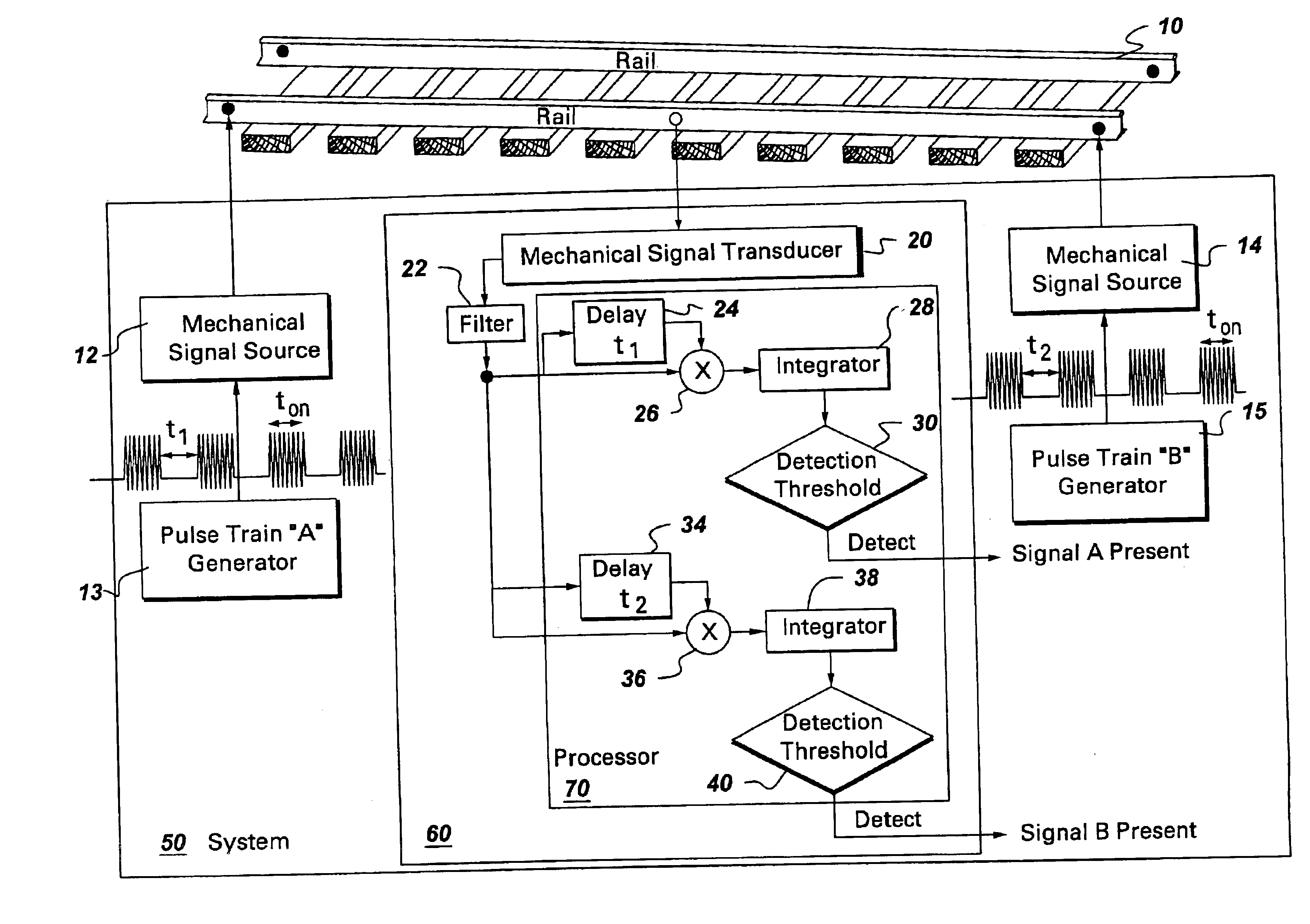
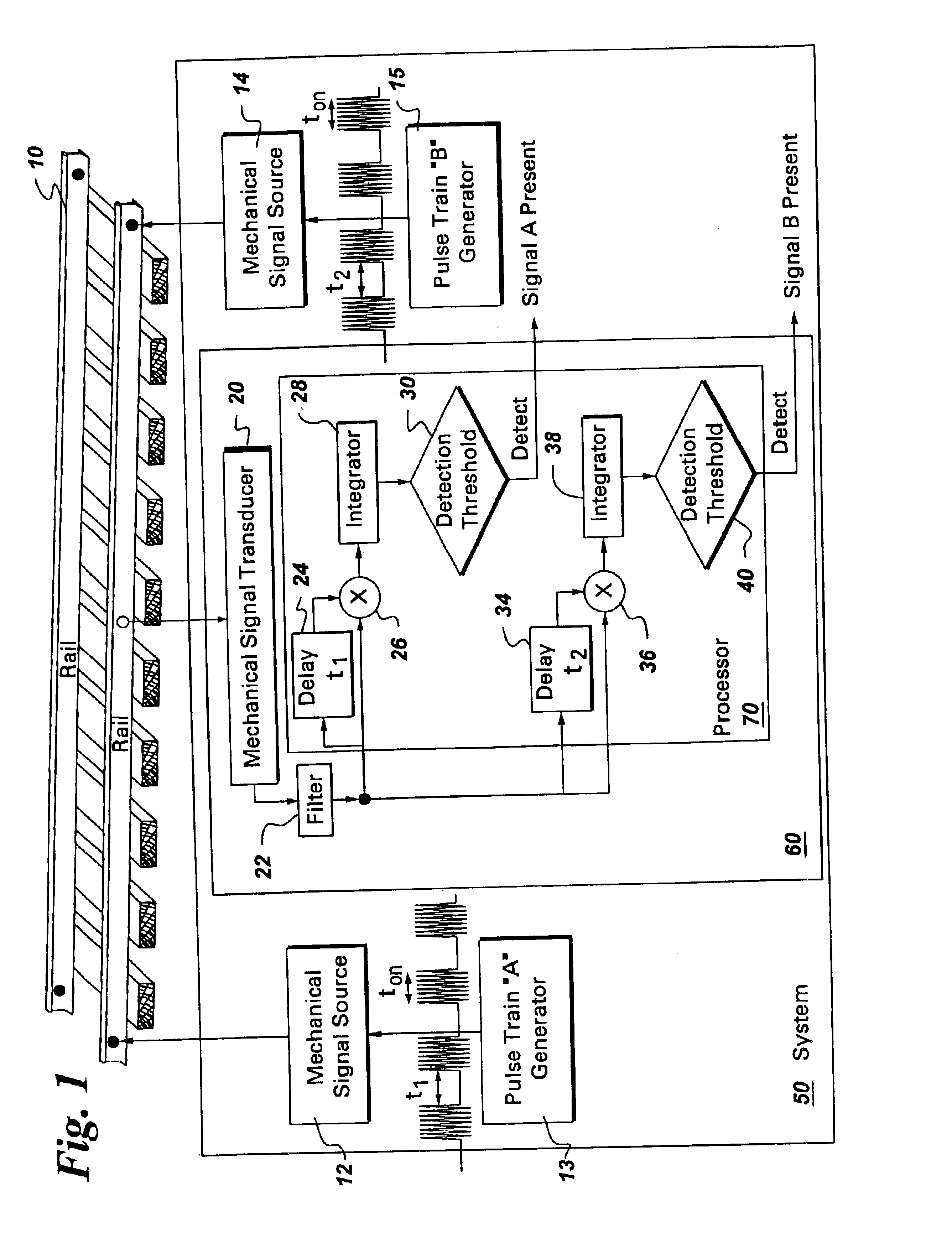
[0011]FIG. 1 is a block diagram of system 50 used for monitoring the integrity of railway track 10. In accordance with one embodiment, system 50 comprises mechanical signal source 12 (or 14) and correlation detector 60. Each component is described in further detail below.

[0012]As used herein, “adapted to”, “configured” and the like refer to mechanical or structural connections between elements to allow the elements to cooperate to provide a described effect; these terms also refer to operation capabilities of electrical elements such as analog or digital computers or application specific devices (such as an application specific integrated circuit (ASIC) that are programmed to provide an output in response to given input signals.

[0013]Mechanical signal source (meaning at least one mechanical signal source) 12 or 14 is coupled to railway track 10 and configured for generating a mechanical signal pulse train (meaning at least one mechanical signal pulse train) over railway track 10, th...


PUM


Abstract

A system to monitor the integrity of a railway track is provided. The system comprises a mechanical signal source and a correlation detector. The mechanical signal source coupled to the railway track and is configured for generating a mechanical signal pulse train over the railway track. The correlation detector monitors the integrity of the railway track by observing the pulse trains transmitted by the mechanical signal sources. If the railway track is intact, then the pulse train will travel to the correlation detector and afford the opportunity for repeatable detection.

Description

BACKGROUND OF THE INVENTION[0001]The invention relates generally to broken rail detection systems, and more specifically to a system and method for active detection of broken rails.[0002]Many approaches exist to monitor the safety of railroad systems and to detect mechanical separation, or a break in the rails. One common approach is the use of electric track circuits in a predefined section or block of track wherein the lack of electrical continuity serves as an indication for railroad breaks. Manual inspection is also typically utilized to detect such rail breaks.[0003]Another approach to detect railroad breaks is to transmit bursts of mechanical energy over the tracks at regular intervals. A transducer coupled to the rail provides an electrical signal representative of the mechanical signal. An energy detector is commonly used to detect the presence of the transmitted pulses and thus determine the integrity of the railroad. One problem with the approach is that the propagation ch...

Claims


Application Information

Patent Timeline
IPC IPC(8): G01V1/00B61L23/04
CPCB61L23/041G01V1/001B61L23/044
Inventor DAVENPORT, DAVID MICHAELHOCTOR, RALPH THOMASVAN STRALEN, NICK ANDREW
Owner GE GLOBAL SOURCING LLC
Why Eureka
Try Eureka