Eureka AIR delivers breakthrough ideas for toughest innovation challenges, trusted by R&D personnel around the world.

Fiber laser based production of laser drilled microvias for multi-layer drilling, dicing, trimming or milling applications

a fiber laser and micro-tube technology, applied in the field of fiber lasers, can solve the problems of fiber lasers that suffer from other problems, limit the power that can be delivered, and in particular the single-mode beam output, and cannot provide the highest output power

Inactive Publication Date: 2006-03-30
HITACHI SEIKO LTD
View PDF4 Cites 88 Cited by
  • Summary
  • Abstract
  • Description
  • Claims
  • Application Information

AI Technical Summary

Benefits of technology

The present invention is about fiber lasers and methods for using them for micro-machining with stacked pulses. The invention includes generating a laser beam output with a sequence of pulses and a method for combining the pulses into a single beam with an inter-pulse interval and an inter-laser interval determined by the initial firing time and the repetition rate of the pulses. The invention also includes a method for generating a laser beam output with a sequence of continuous wave, pseudo-continuous wave, and pulse sequence output components from multiple fiber lasers. The combination of the output components from the fiber lasers can be performed using optical elements that redirect the output components' axes into a single region of a second optical element. The invention also includes a multi-pumped fiber laser that includes an optical fiber, first and second end structures, and a resonant optical cavity formed by the first and second end structures.

Problems solved by technology

Fiber lasers also suffer from other problems, which are often shared with or stem from the lasers used to pump the fiber lasers.
Considering the problems arising from the lasers used to pump the fiber lasers, the Diode Pumped Solid State (DPSS) lasers currently and commonly used to drive fiber lasers produce a single mode beam and typically suffer from pointing and drift instabilities as well as from limits on the power that can be delivered by the DPSS laser, which is typically in the range of 10 Watts @ 355 nm (nanometers) and 2 to 3 watts @266 nm.
That is, and for example, DPSS lasers may produce useful Gaussian and TEM00 mode beam outputs as well as a single mode beam outputs, but these modes, and in particular the single mode beam output, do not provide the highest output power.
Beam shaping technology and uniform flat top beams, however, require a stable laser input beam and, discussed below, it is difficult to obtain a stable output beam from a DPSS laser.
For example, the DPSS lasers commonly used for drilling multi-layered printed circuit boards for producing chip packaging / carriers generate a single mode output beam that becomes unstable when certain critical parameters, such as pump current and pulse repetition rate, are changed, or because of certain conditions arising from operation of the laser, such as thermal lensing or heating due to power dissipation.
Such variations in the laser parameters may result, for example, in long term beam movement or drift and beam drift and pointing instability drift.
Long term beam movement or drift may result in system down time since the optical beam delivery system must be realigned when the beam displacement exceeds tolerable limits, while short term beam movement or drift will typically result in distortion of the beam profile, the formation of hot and cold spots in the beam, and a loss in efficiency and in the power levels delivered by the laser beam.
Certain other problems are common and critical to fiber laser systems as well as to the laser machining systems of the prior art and one of the most significant of these problems is control of the laser beam pulse width, repetition rate, frequency and power characteristics to achieve the optimum effect at the workpiece being machined.
The performance of DPSS UV lasers is limited in its processing capabilities, however, due to its beam propagation factor, which is typically in the range M2=<1.2, as well as by the fact that the drilling process is limited solely to UV ablation.
UV DPSS lasers are also limited in their ability to dice or cut multilayered printed circuit board materials and other semiconductor wafer materials due to the etch rate of materials in of UV wavelengths, which is a function of the absorption of UV light in the materials, and because of variations or differences in the ablation energy density required for different materials as the DPSS laser cuts through the single and multiple layers of different materials.
It must also be noted that while the etch rate of a given laser can be increased by increasing the laser output power, repetition rate or pulse width, or any combination thereof, such efforts can as easily be counterproductive for a number of reasons.
In addition, simply increasing the power delivered to the target material may cause undesired effects at the target material, such as loss of control of the drilling or cutting dimensions, ragged cuts, blocking of the laser beam by the ablated material, thereby actually reducing the power delivered to the material, and unwanted deposits of ablated material in the drilling or cutting area, thus damaging the surface of the target material.
As discussed above, UV DPSS lasers also have problems with beam pointing and drift stability because the laser rods are diode pumped, which causes the rods to heat and thereby results in problems with thermal drift and pointing stability.
The thermal lensing and harmonic generation processes required to convert the fundamental IR radiation of the lasers to the UV range required for the desired laser output beam also creates further issues with stability.
In addition, the optical efficiency of UV DPSS lasers is relatively low due to inefficient diode pumping methods and the resulting energy losses are translated into heat, which further aggravates the problems with thermal drift and pointing stability.
As also discussed above, UV DPSS lasers are limited to operating in either a pulsed mode output or a continuous mode output but a UV DPSS laser cannot generate both mode outputs simultaneously, thereby limiting the ability of a system using UV DPSS lasers to generate the output beamforms most suited for different applications and materials.
UV DPSS lasers also suffer from beam propagation issues due to its beam propagation value which is approximately M2=<1.2, which creates problems when using beam shaping technology such as diffractive optical elements and holographic optical elements by causing ringing effects.
The ringing effects cannot be compensated for and generate undesirable laser beam imaging properties at the target material being processed.

Method used


Image

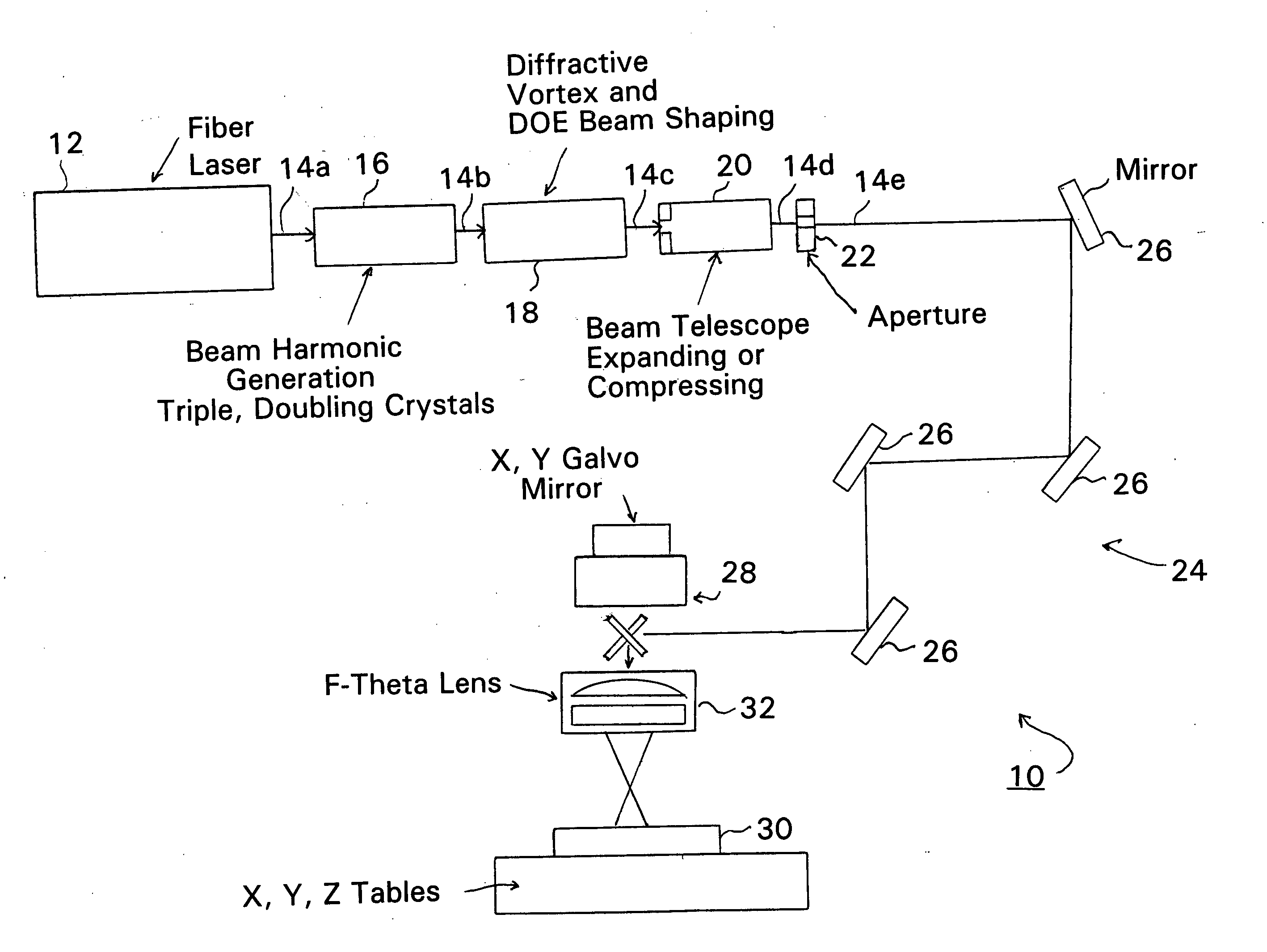
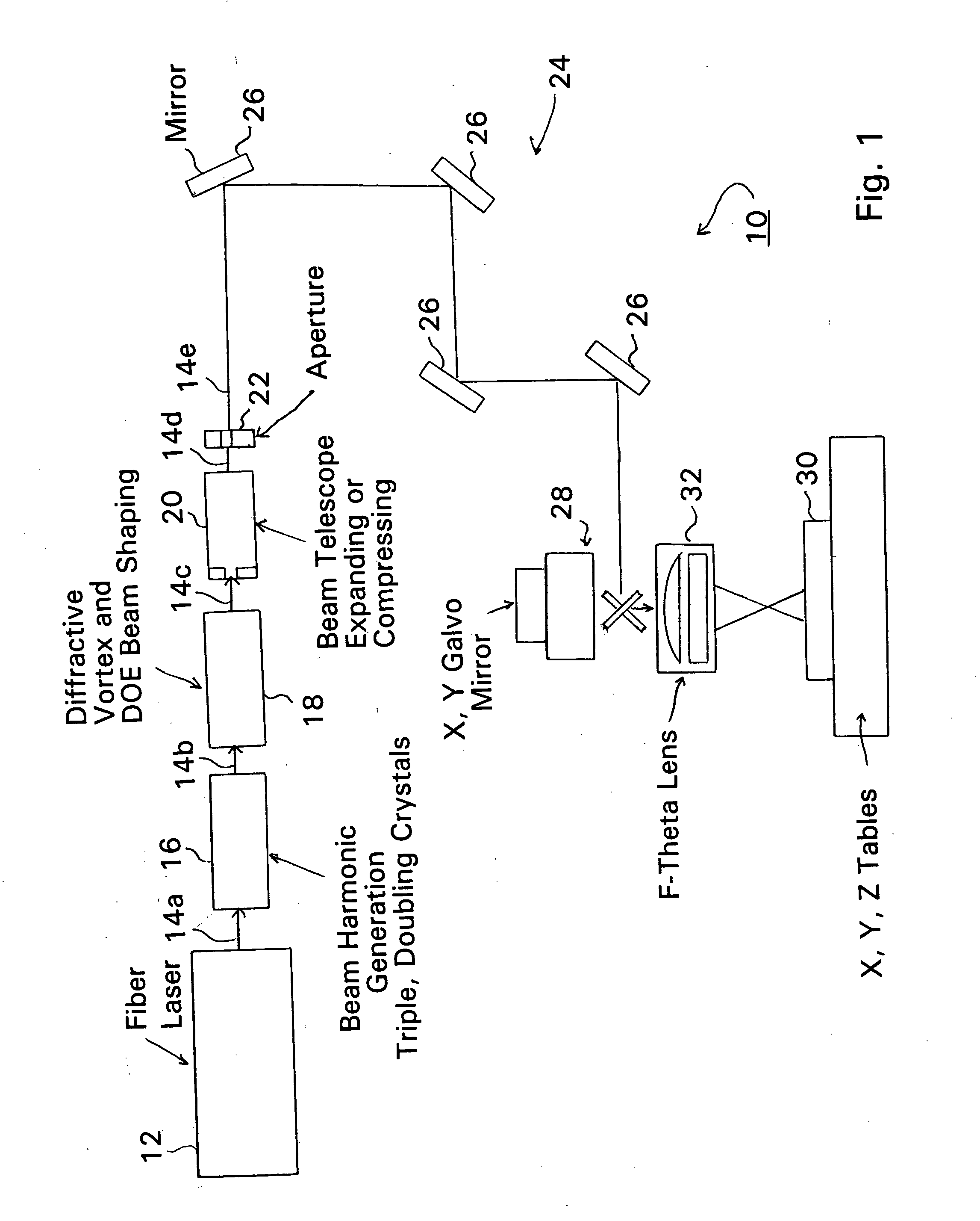
  • Fiber laser based production of laser drilled microvias for multi-layer drilling, dicing, trimming or milling applications
  • Fiber laser based production of laser drilled microvias for multi-layer drilling, dicing, trimming or milling applications
  • Fiber laser based production of laser drilled microvias for multi-layer drilling, dicing, trimming or milling applications

Examples


Embodiment Construction

[0044] As described above, the present invention is directed to methods and apparatus for constructing fiber lasers and to methods and apparatus using fiber lasers to generate laser beams having selectable pulse width, repetition rate, frequency and power characteristics for micro- and nano-machining of various materials.

[0045] As will be described in the following, the method of laser micro- / nano-drilling with stacked pulse beams or with beams comprised of combinations of one or more of continuous, pulsed continuous or pulse beam components may be performed with appropriately triggered and driven single lasers, including multipumped lasers, or with appropriately triggered and driven fiber lasers. Examples of such lasers would include a high power non-excimer laser, such as a non-diode pumped Nd:YAG, Nd:YLF, Nd:YAP or Nd:YVO4 solid state laser operating at a repetition rate >1 kHz with a range of operational wavelengths from 180 nm to 4000 nm or a diode pumped fiber laser construct...


PUM

PropertyMeasurementUnit
wavelengthsaaaaaaaaaa
poweraaaaaaaaaa
poweraaaaaaaaaa

Abstract

Fiber lasers and methods for constructing and using fiber lasers for micro- / nano-machining with output beams including stacked pulses and combinations of continuous wave, pseudo-continuous wave and pulse sequence components.

Description

CROSS REFERENCE TO RELATED APPLICATIONS [0001] The present patent application is related to and claims benefit of Provisional Patent Application Ser. No. 60 / 613,763 filed 28 Sep. 2004 by Todd E. Lizotte and Orest Ohar for FIBER LASER BASED PRODUCTION OF LASER DRILLED MICROVIAS FOR MULTI-LAYER DRILLING, DICING, TRIMMING OR MILLING APPLICATIONS and Provisional Patent Application Ser. No. 60 / 620,271 filed 18 Oct. 2004 by Todd E. Lizotte and Orest Ohar for MICRO / NANO MACHINING, WELDING, DICING, DRILLING SINGLE LAYER AND MULTIPLE LAYER MATERIALS WITH VARYING CHEMICAL COMPOSITION WITH FIBER LASERS AND FIBER LASER BEAM DELIVERY TECHNOLOGY.FIELD OF THE INVENTION [0002] The present invention is related to the use of fiber lasers in micro- and nano-machining of various materials and, more specifically, to methods and apparatus for generating laser beams to drive fiber lasers and to methods and apparatus using multiple fiber lasers to generate laser beams having selectable pulse width, repetit...

Claims


Application Information

Patent Timeline
Patent Type & Authority Applications(United States)
IPC IPC(8): B23K26/00H01S3/30
CPCB23K26/0604H05K3/0026B23K26/0639B23K26/0648B23K26/0665B23K26/123B23K26/385G02B6/0008H01S3/005H01S3/0057H01S3/067H01S3/0804H01S3/0817H01S3/094011H01S3/094076H01S3/09415H01S3/10046H01S3/11B23K26/063B23K26/064B23K26/0622B23K26/389B33Y30/00H01S3/0092H01S3/1024
Inventor LIZOTTE, TODD E.OHAR, OREST
Owner HITACHI SEIKO LTD
Why Eureka
Eureka Blog
Learn More