AI technical title is built by Patsnap AI team. It summarizes the technical point description of the patent document.
a multi-functional, fastening technology, applied in the direction of snap fasteners, buckles, machine supports, etc., can solve the problems of increasing production costs, both producers and users, and not liking the resulting increase of costs, so as to enhance the performance and convenience of the device, enhance the effect of sucking and attaching performan
Inactive Publication Date: 2005-05-24
HUANG YEA YEN
View PDF7 Cites 61 Cited by
Summary
Abstract
Description
Claims
Application Information
AI Technical Summary
This helps you quickly interpret patents by identifying the three key elements:
Problems solved by technology
Method used
Benefits of technology
Benefits of technology
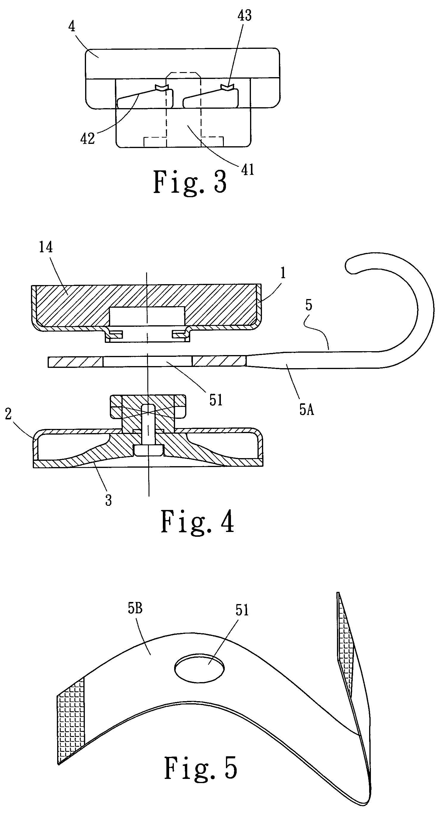
[0006]It is an objective of the present invention to provide a multiple-function hanging and fastening device that is capable of magnetic attraction, disc suction and screw tightening functions simultaneously, characterized in that, on two sides or one side of the device is installed a magnet and a rubber sucker for selectively sucking onto a computer set, an electrical appliance, a decorated wall, a metal panel or glass panel or a smooth panel of a car or a piece of furniture. On the same side of the device is installed simultaneously a magnet and a rubber sucker to enhance its sucking and attaching performance. The main unit is capable of combining a hanging hook, a Velcro band, a wire bundling band or a multiple-function palm figure accessory for gripping purposes, to enhance its performance and convenience.
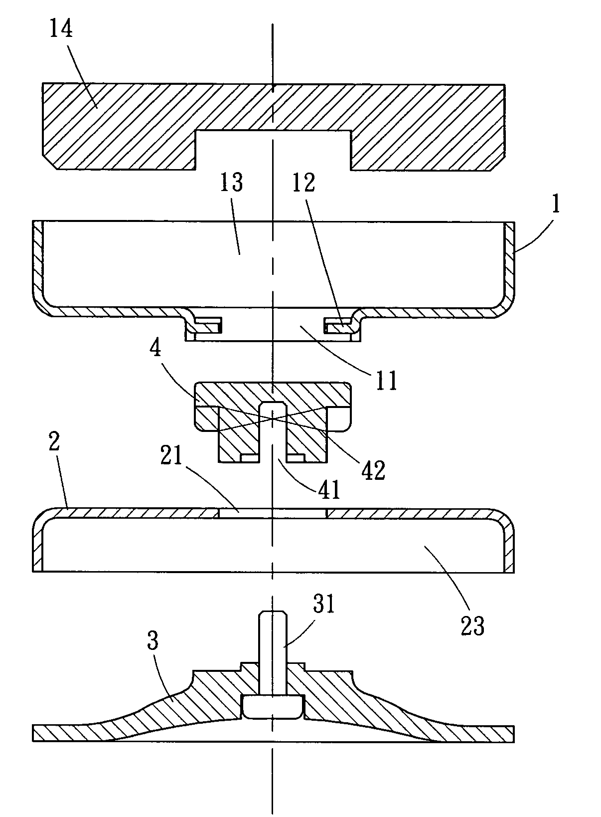
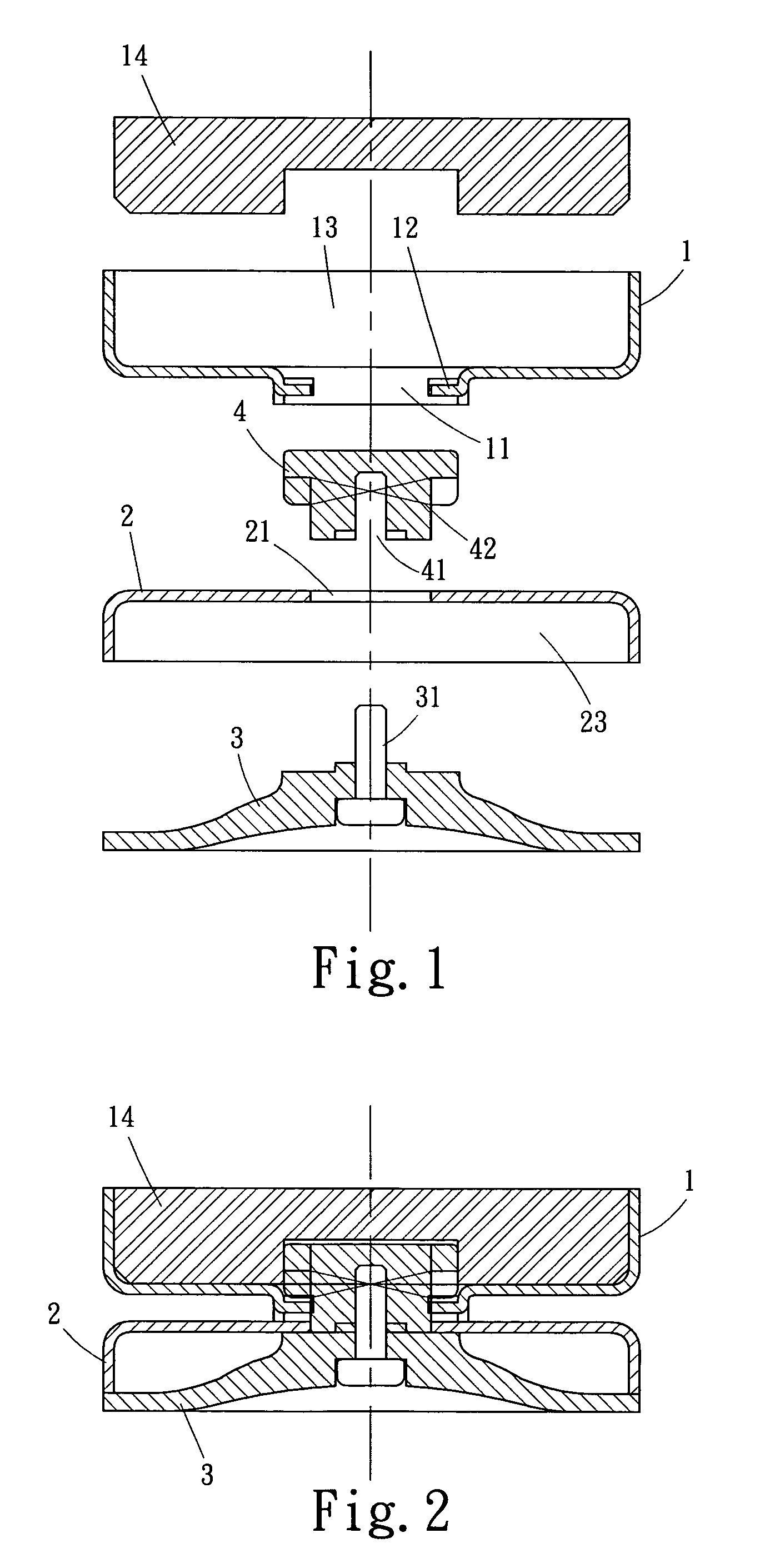
[0009]The rubber sucker (3) has its extended part of screw bolt (31) running through the through hole (21) on the lower casing (2), selectively screwed into the thread hole (41) at one end of the brake block (4), tightening the rubber sucker (3) and the brake block (4) onto the lower casing (2). The lower casing (2) containing the rubber sucker (3) and the brake block (4) may have its brake block (4) inserted into the through hole (11) on the upper casing (1), the protruded block (12) and the brake block (4) therein in mesh with the tapered face (42) on the inside of top end. By turning the upper casing (1) and the lower casing (2), the protruded block (12) and the tapered face (42) of the brake block (4) creates a dislocation, arrested by the brake groove (43), pulling up the rubber sucker (3) to close the upper and lower casings (1), (2) and enhance the sucking strength of the rubber sucker (3).
Problems solved by technology
Therefore, to meet user's different requirements, the producer has to increase production costs.
Both producers and users will not like the resulting increase of costs.
Method used
Image
Click on the blue label to locate the original text in one second.
Reading with bidirectional positioning of images and text.
Examples
Embodiment Construction
[0043]In the foregoing structure, the present invention can also be embodied in a design to include a magnet and a rubber sucker simultaneously on a single side of a casing, please refer to FIG. 13, at a center of one side of a casing (8) is reserved a depressed groove (81) to accommodate a rubber sucker (83), on two sides are also reserved a depressed groove (82) to accommodate a magnet (84), to enable suction function simultaneously by the rubber sucker (83) and the magnet (84), at a center of the casing (8) is a through hole (85) to be inserted by one end of a moving block (86), as shown in FIGS. 14 and 15.
[0044]An extended rod (831) is planted on the rubber sucker (83), or is selectively fixed to a center hole (861) of the moving block (86) to combine with the moving block (86) as one unit, on one end of the moving block (86) is a thread hole (862), enabling the screw bolt (871) of the nut (87) outside the casing (8) to be screwed into the thread hole (862), so it will properly ...
PUM
Abstract
A multiple-function hanging and fastening device has multiple functions of an attracting magnet, a sucking sucker and a tightening screw, characterized in that, at least one side of the device has a magnet and a rubber sucker, for selective sucking on to a computer, electrical appliance, decorated wall surface, a metal panel of a car or a piece of furniture, a glass panel or a smooth plate, and selectively, a magnet and a rubber sucker are installed on a same side to increase its suction performance, and the outside or structural body of the casing is provided with a screw hole permitting the insertion of a screw to fasten onto an ordinary wall surface, and, one of accessories, including a hanging hook, a Velcro band, a wire bundling band and a multiple-function gripping palm figure, can be combined onto the main unit to extend its range of applications, obviously, its structure and applications have multiple functions and convenience.
Description
FIELD OF THE INVENTION[0001]A structural design of a hanging device that can be attached to a computer, electrical appliance, decorated wall surface, metal panel of a car or piece of furniture, glass or smooth plate or screwed to an ordinary wall, its main unit is capable of containing a hanging hook, Velcro band, wire bundling band, a gripping palm figure, and such accessories, for the purpose of hanging objects, fastening particular articles, sorting out computer cable, or fixing a pipe, to extend its applications, functions and convenience.DESCRIPTION OF THE PRIOR ART[0002]Generally, a hanging hook or a sucker is used to suck onto a smooth surface such as a glass, or a magnetic tab is used to attach onto a metal panel, or a wire clip or positioning bolt is fastened on a wall to fasten a wire or pipe, in the use of computer, installation of network circuits, installation of telephone, attachment of data on a metal plate, marking on a metal plate, exhibition of products, public not...
Claims
Application Information
Patent Timeline
Application Date:The date an application was filed.
Publication Date:The date a patent or application was officially published.
First Publication Date:The earliest publication date of a patent with the same application number.
Issue Date:Publication date of the patent grant document.
PCT Entry Date:The Entry date of PCT National Phase.
Estimated Expiry Date:The statutory expiry date of a patent right according to the Patent Law, and it is the longest term of protection that the patent right can achieve without the termination of the patent right due to other reasons(Term extension factor has been taken into account ).
Invalid Date:Actual expiry date is based on effective date or publication date of legal transaction data of invalid patent.

