Eureka AIR delivers breakthrough ideas for toughest innovation challenges, trusted by R&D personnel around the world.

Method and apparatus for a variable displacement internal combustion engine

a technology of internal combustion engine and variable displacement, applied in the direction of machines/engines, electrical control, valve arrangements, etc., can solve the problems of undesirable cycle or continuous switching (busyness), and achieve the effect of reducing the potential for cycling and reducing the busyness of operating mode switching

Inactive Publication Date: 2005-05-24
GM GLOBAL TECH OPERATIONS LLC
View PDF3 Cites 11 Cited by
  • Summary
  • Abstract
  • Description
  • Claims
  • Application Information

AI Technical Summary

Benefits of technology

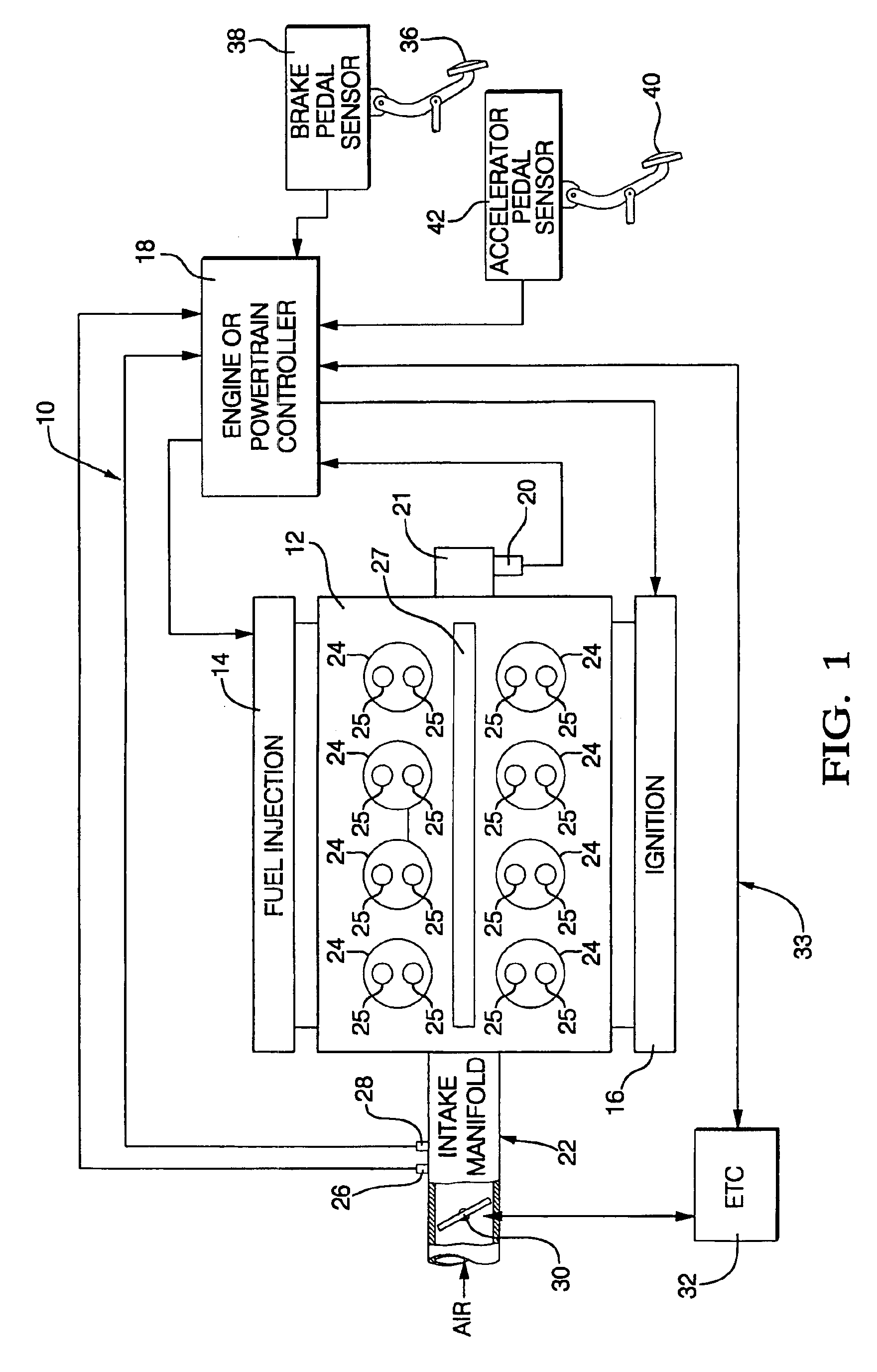
[0006]The present invention includes methods and apparatus that allow the operation of a vehicle with a variable displacement engine to be transparent to a vehicle operator. In the preferred embodiment of the present invention, an eight-cylinder internal combustion engine (ICE) may be operated as a four-cylinder engine by deactivating four cylinders. The cylinder deactivation occurs as a function of load or torque demand by the vehicle. An engine or powertrain controller will determine if the ICE should enter four-cylinder mode by monitoring the load and torque demands of the ICE. If the ICE is in a condition where it is inefficient to operate with the full complement of eight cylinders, the controller will deactivate the mechanisms operating the valves for the selected cylinders and also shut off fuel (and possibly spark in the case of a gasoline engine) to the cylinders. The deactivated cylinders will thus function as air springs to reduce pumping losses.
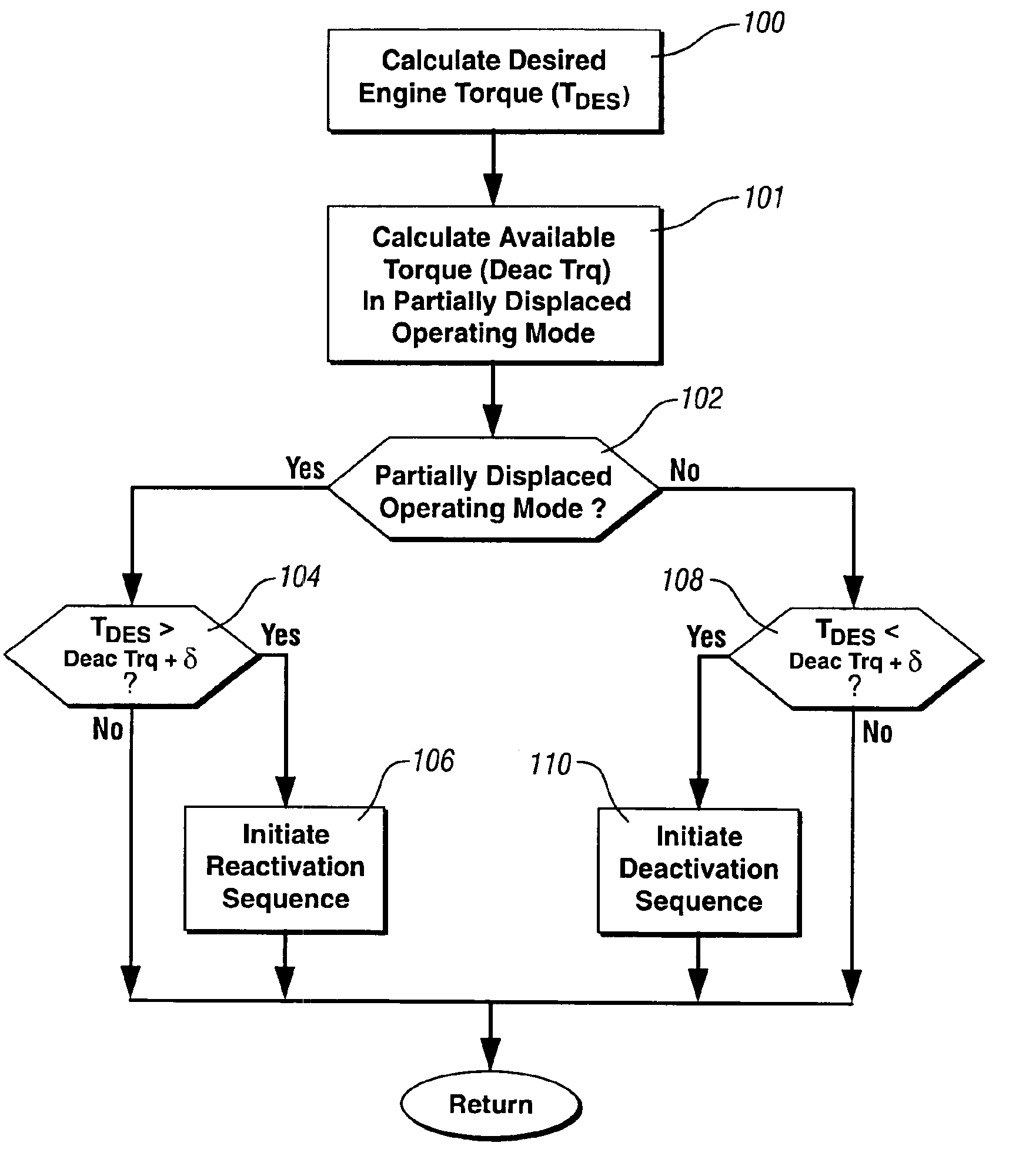
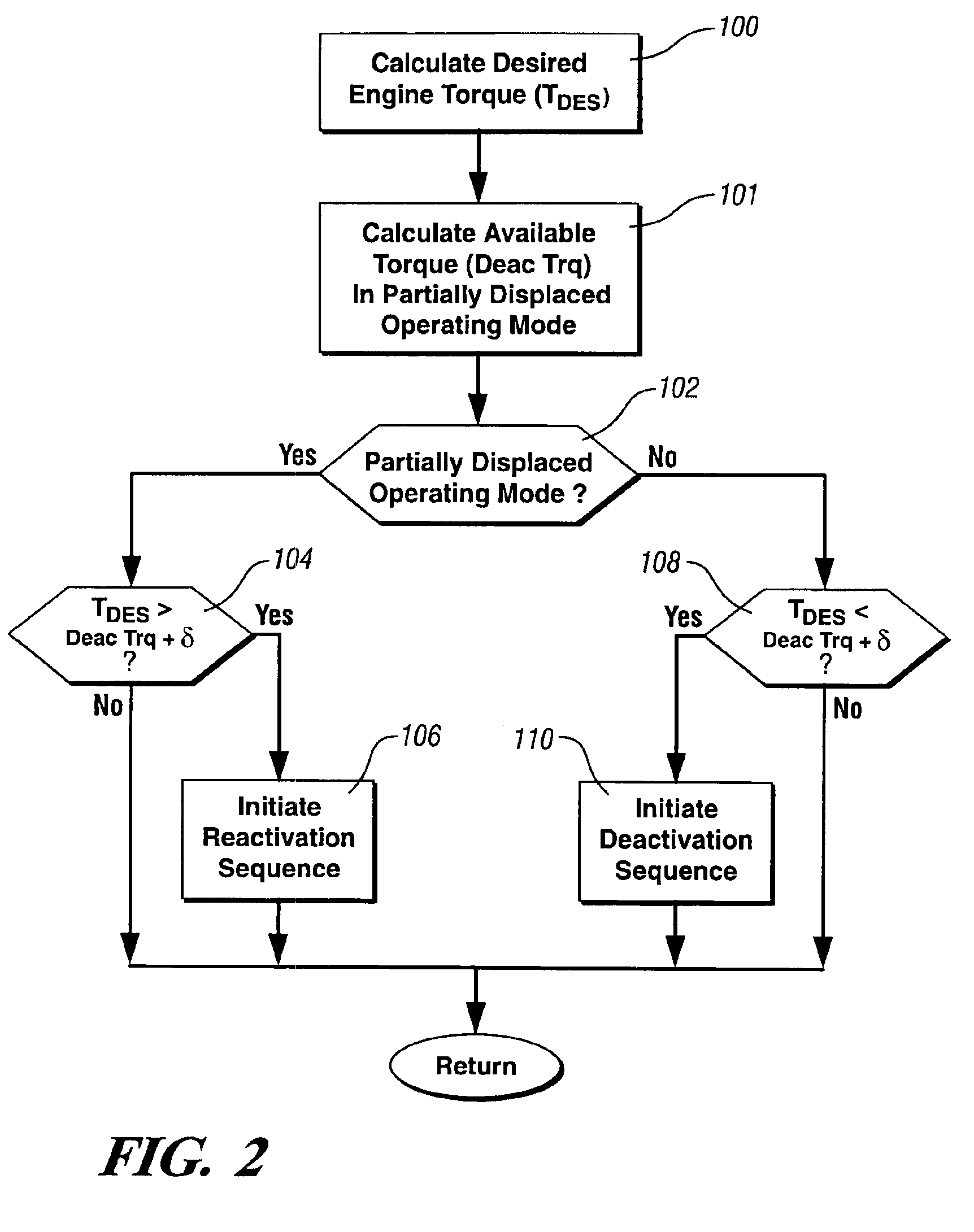
[0009]The present invention reduces the busyness of operating mode switching or cycling by monitoring the requested or commanded torque from an operator via the position and rate of change of an accelerator pedal. When operating conditions that generate busyness are detected, the commanded torque is incremented by a hysteresis calibration value to decrease the potential for cycling.

Problems solved by technology

Continued switching or cycling (busyness) is undesirable in a variable displacement ICE.

Method used


Image

  • Method and apparatus for a variable displacement internal combustion engine
  • Method and apparatus for a variable displacement internal combustion engine
  • Method and apparatus for a variable displacement internal combustion engine

Examples


Embodiment Construction

[0012]FIG. 1 is a diagrammatic drawing of the vehicle control system 10 of the present invention. The control system 10 includes a variable displacement ICE 12 having fuel injectors 14 and spark plugs 16 controlled by an engine or powertrain controller 18. The ICE 12 may comprise a gasoline ICE or any other ICE known in the art. The ICE 12 crankshaft 21 speed and position are detected by a speed and position detector 20 that generates a signal such as a pulse train to the engine controller 18. An intake manifold 22 provides air to the cylinders 24 of the ICE 10, the cylinders 24 having valves 25. The valves 25 are further coupled to an actuation apparatus such as a camshaft 27 used in an overhead valve or overhead cam configuration that may be physically coupled and decoupled to the valves 25 to shut off air flow through the cylinders 24. An air flow sensor 26 and manifold air pressure sensor 28 detect the air flow and air pressure within the intake manifold 22 and generate signals ...


PUM


Abstract

An engine control system including a variable displacement internal combustion engine, a plurality of cylinders located in the internal combustion engine, a plurality of fuel injectors for providing fuel to the plurality of cylinders, a plurality of valves coupled to the plurality of cylinders, the plurality of valves controlling the air flow in and out of the cylinders, an actuation apparatus for actuating the plurality of valves, an intake manifold coupled to the internal combustion engine, a throttle coupled to the intake manifold, a controller electronically coupled to the fuel injectors, an accelerator pedal position sensor electronically coupled to the controller, and where the controller determines the number of the cylinders to provide with fuel and air and a desired engine output torque based on the accelerator pedal position sensor and a hysteresis value.

Description

[0001]This application is a continuation in part of, U.S. patent application Ser. No. 10 / 104,111, filed on Mar. 22, 2002 now U.S. Pat. No. 6,782,865, and U.S. patent application Ser. No. 09 / 847,106, filed May 3, 2001.TECHNICAL FIELD[0002]The present invention relates to the control of internal combustion engines. More specifically, the present invention relates to methods and apparatus to provide for the control of a variable displacement internal combustion engine.BACKGROUND OF THE INVENTION[0003]Present regulatory conditions in the automotive market have led to an increasing demand to improve fuel economy and reduce emissions in present vehicles. These regulatory conditions must be balanced with the demands of a consumer for high performance and quick response in a vehicle. Variable displacement internal combustion engines (ICEs) provide for improved fuel economy and torque on demand by operating on the principal of cylinder deactivation.[0004]During operating conditions that requ...

Claims


Application Information

Patent Timeline
Patent Type & Authority Patents(United States)
IPC IPC(8): F02D17/00F02D17/02F01L13/00F02D37/02F02D41/00F02D41/36F02D45/00
CPCF01L13/0005F02D17/02F02D37/02F02D41/0087F02D2250/18F02D41/187F02D2200/602F02D2200/703
Inventor MATTHEWS, GREGORY P.FOLKERTS, CHARLES H.
Owner GM GLOBAL TECH OPERATIONS LLC
Why Eureka
Eureka Blog
Learn More