
Slot-type gaming machine with variable drop zone symbols

a slot machine and drop zone technology, applied in the field of slot machines, can solve the problems of higher mechanical maintenance costs of machines, not as well suited to gaming as traditional slot machines, and less attractive to the gaming public, and achieve the effects of high jackpot oriented, high probability of winning, and high payout probability

Inactive Publication Date: 2005-05-24
DIGIDEAL
View PDF14 Cites 26 Cited by
  • Summary
  • Abstract
  • Description
  • Claims
  • Application Information

AI Technical Summary

Benefits of technology

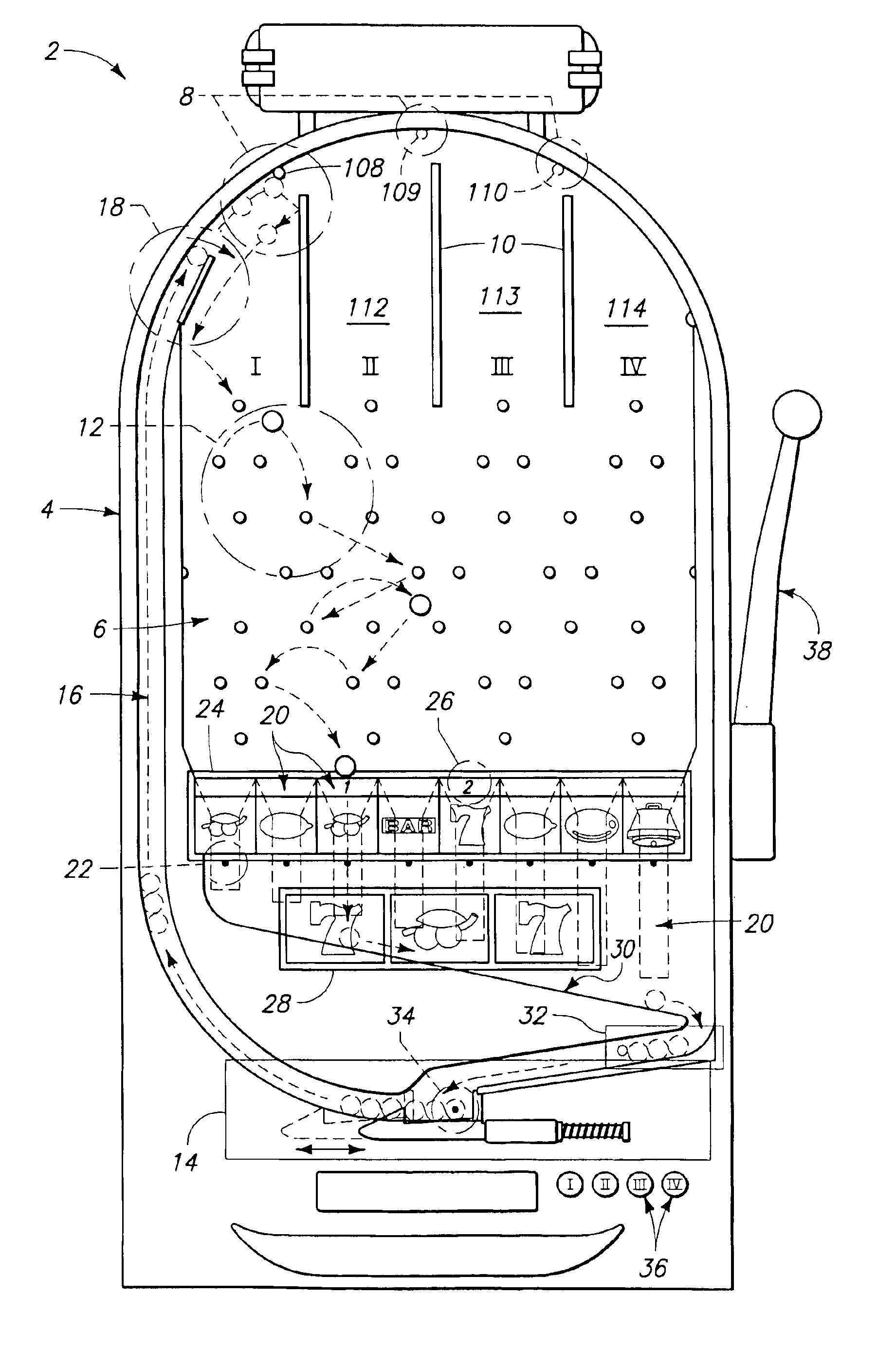
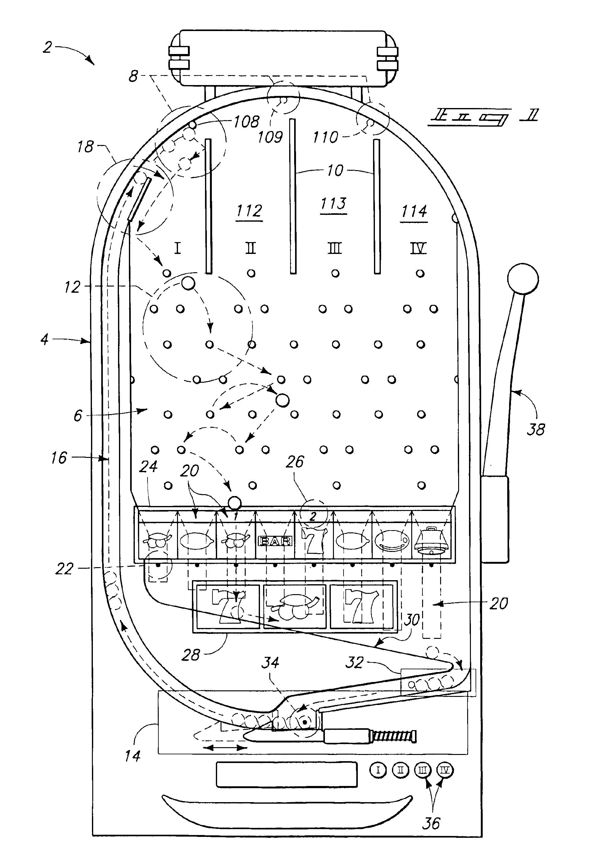
[0013]The exit or other detector positions have a corresponding symbol which is associated or assigned to the position to enhance play. The symbol can be displayed on detector displays using suitable symbol representations, such as represented on a liquid crystal display, at or near an exit or other detector position. The symbol display, can be configured to light up or otherwise indicate when a ball passes through or is otherwise detected at that position. A small indicator, such as one or more LED's, above each symbol can be used to reflects how many balls fell into a particular position (providing some did). This is used to eliminate doubt which can otherwise arise as to which position has been scored, and to how many balls passed through the associated posItion. A larger payline display, simulating the payline of a traditional slot machine, shows the series of symbols selected by the balls passing through the exit positions.
[0024]The machine of the present invention also allows for a greater number of symbols to be displayed than a traditional, reel based, slot machine. The reel based machines are limited to displaying the number of symbols that can be fit on the reel. In a three (3) reel machine with eleven (11) symbols per reel there are 1,331 possible combinations that can ever be displayed on the payline. In the present invention it is easy to store many symbols for electronic display. In a machine with eight (8) exit positions and 25 possible symbols per exit position there are over 150 billion combinations for display on the exit position display. This larger number of possible combinations makes it possible for the present invention to pay out over a larger range of combinations and would allow a single machine to have the potential to pay out a very large jackpot.
[0025]The present invention should have a very wide appeal to the gaming establishments as it has an overtly visible “mechanical” element, balls launching and freely dropping through the playing field, yet very low maintenance. The maintenance is low because other than simple mechanical switches and a ball ejecting system, the machine is dependent on non-mechanical hardware and software for most of its operation.
[0026]Still other versions and aspects of the invention can be implemented by combining the drop zone style game machine described herein in a gaming machine which also includes a more traditional reel-style slot machine. One or more reels having the reel symbols included thereon can be presented in the traditional slot machine fashion. The probability combinations can be greatly enhanced by having a secondary drop zone section on the machine with the traditional slot machine reels. The secondary drop zone section can be played concurrently, as a bonus round, combined in a single payline determination using both symbol sets, otherwise combined or sequenced to enhance the player'enjoyment and anticipation. The added mathematical probability options are greatly enhanced and this allows the casino operator to offer greatly enhanced maximum jackpot amounts without having the added cost and complexity of connecting numerous slot machines into a mega-jackpot pool as is a common and costly procedure being used widely in the casino industry.

Problems solved by technology

While pachinko machines have seen a great deal of popularity in Asia, they are not as well suited for gaming as the traditional slot machine.
Even though the new machines simulated the mechanical slots in every way and used the same random number generating circuit and yielded the same percentages as the mechanical slot machines, they were less attractive to the gaming public.
The biggest problem with the mechanical or electronic slot machines that have mechanical reels is that they have higher mechanical maintenance costs than machines with video displays in place of spinning reels.
While prior art machines that replaced the spinning reels with video displays had lower mechanical maintenance costs, they were also less attractive to gamers.
Another problem with traditional slot machines is their size, due to the space requirements of the mechanical reels.
Traditional slot machines take up a great deal of floor space and are generally not well suited to being wall mounted.
Yet another problem with traditional slot machines is that the limited number of possible combinations of symbols limits the size of a jackpot that can be offered.
This is relatively complicated and requires greater costs in setting up and operating the machines.

Method used


Image

  • Slot-type gaming machine with variable drop zone symbols
  • Slot-type gaming machine with variable drop zone symbols
  • Slot-type gaming machine with variable drop zone symbols

Examples


first embodiment

Generally

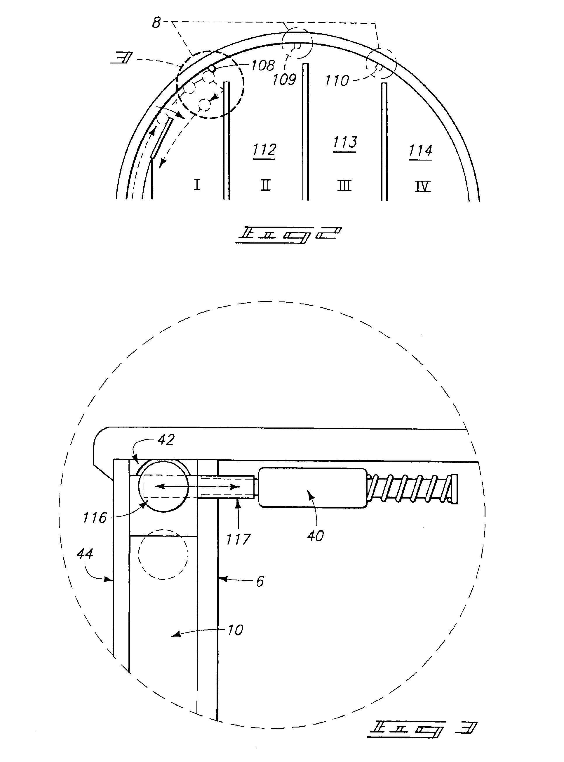
[0038]The game machine of the present invention is shown generally at 2 in FIG. 1. The present invention comprises a generally upright gaming cabinet 4, the upper portion of which houses the playing field 6 which in turn is covered by a transparent front glass 44. At the top of playing field 6, there are three zone deflectors 108, 109, and 110, just below and slightly to the right of each deflector there is a zone divider wall 112, 113, and 114. Zone deflectors 108, 109, and 110 along with zone divider walls 112, 113, and 114 divide the upper portion of the playing field into drop zones I, I, III and IV.

[0039]The middle portion of playing field 6 is comprised of a maze of deflector pegs 12. Generally, the maze of deflector pegs 12 is arranged so it would take a ball 2-4 seconds to fall through the maze. There are eight exit positions 20 at the bottom of playing field 6 under the maze of deflector pegs 12. Each exit position 20 has an exit position sensor 22 associated with ...


PUM


Abstract

A game machine (2, 200) which includes a playing field (6, 301) traversed by objects, such as balls (320). The playing field can have plural drop zones (381-383) which can be selected by the player using deflectors (108-110) that control where the balls are launched. Detectors (22, 392) indicate scoring positions assumed by the balls. A payline display (28, 335) displays scored events. A symbol selector is included to select symbols which are variably assigned to the scoring positions and displayed on displays (20, 397). Balls score symbols which can be displayed in the payline display and affect winning or bonus play. Game machine (200) includes traditional slot machine reels which can work in conjunction therewith.

Description

CROSS REFERENCE TO RELATED APPLICATIONS[0001]This application is a continuation of U.S. patent application Ser. No. 10 / 198,431, filed Jul. 16, 2002, (U.S. Pat. No. 6,641,137, Nov. 4, 2003); which is a continuation of U.S. patent application Ser. No. 09 / 813,513, filed Mar. 20, 2001, (U.S. Pat. No. 6,419,225, Jul. 16, 2002); which was a continuation of U.S. patent application Ser. No. 09 / 128,960, filed Aug. 4, 1998, (U.S. Pat. No. 6,203,009, issued Mar. 20, 2001), which was a continuation-in-part of prior U.S. patent application Ser. No. 08 / 649,821 filed May 17, 1996 (U.S. Pat. No. 5,788,230, Aug. 4, 1998). Priority under 35 U.S.C. § 120 is claimed with regard to said prior applications. Said prior applications are also incorporated by reference hereinto in their entirety.TECHNICAL FIELD[0002]The field of this invention is slot-type gaming machines having a drop zone portion which has one or more dropping balls or other dropping objects which can be received at different positions to ...

Claims


Application Information

Patent Timeline
IPC IPC(8): A63F7/02G07F17/34G07F17/38G07F17/32A63F7/00A63D13/00
CPCA63F7/022G07F17/34G07F17/3262G07F17/3297G07F17/32A63F2007/0064
Inventor SINES, RANDY D.KRISE, DAVID A.
Owner DIGIDEAL
Learn More