Ink jet printing apparatus, ink jet printing method, program, and printing medium

a technology of ink jet printing and printing apparatus, which is applied in the direction of digitally marking record carriers, visual presentation using printers, instruments, etc., can solve the problems of increasing affecting the quality so as to prolong the life of the nozzle, reduce the cost of the printing apparatus, and reduce the amount of data

Inactive Publication Date: 2005-05-24
CANON KK
View PDF21 Cites 18 Cited by
  • Summary
  • Abstract
  • Description
  • Claims
  • Application Information

AI Technical Summary

Benefits of technology

[0023]It is an object of the present invention to provide an ink jet printing apparatus and method which uses a simple arrangement using dot patterns corresponding to common gradation patterns based on the systematic dither method, to prevent the use of only particular nozzles in a print head, thus delaying the degradation of images or extending the lifetime of the nozzles for stable printing over a long period, as well as a program for this printing method.

Problems solved by technology

However, with the increased resolution of printed images, an enormous amount of data must be processed in the printing apparatus.
Thus, with a print system composed of an image processing section and an ink jet printing section, the throughput of the whole system may decrease sharply because of the speed at which the image processing section processes data or the speed at which the image processing section transfers data to the ink jet printing section.
This may increase the cost of the printing apparatus.
However, for the conventional ink jet printing apparatus based on the serial scan method using the systematic dither process, when examining the durability of the print head achieved if images are constantly printed over a long period, the inventors found that an adverse effect on the durability appears periodically in the plurality of nozzles in the print head.
In the above conventional example, if the systematic dither method is used to print images constantly over a long period, the nozzles in the print head are not uniformly degraded.

Method used


Image

  • Ink jet printing apparatus, ink jet printing method, program, and printing medium
  • Ink jet printing apparatus, ink jet printing method, program, and printing medium
  • Ink jet printing apparatus, ink jet printing method, program, and printing medium

Examples


Embodiment Construction

[0089]A preferred embodiment of the present invention will be described below in detail with reference to the accompanying drawings.

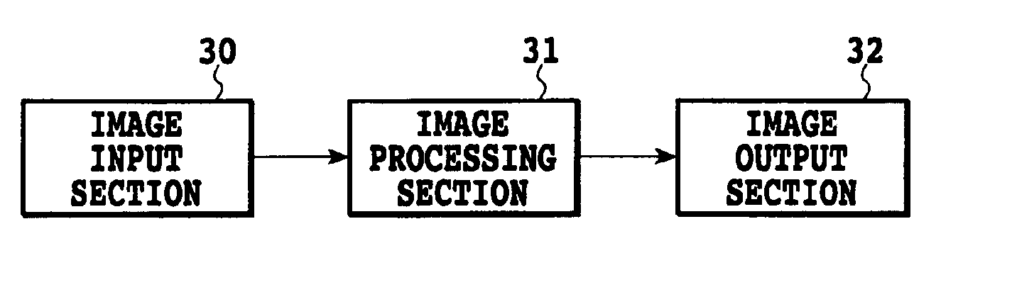
[0090]FIG. 1 is a block diagram showing schematically a configuration of an image processing system according to a typical embodiment of the present invention. In FIG. 1, reference numeral 30 denotes an image input section to which multivalued image data from image input equipment such as a scanner or a digital camera or from various storage medium such as a hard disk is inputted. Reference numeral 31 denotes an image processing section that executes image processing on the multivalued image data inputted through the image input section 30 to convert it into image data expressed by n values. Reference numeral 32 is an image output section to which the n-valued image data provided by the image processing section 31 is inputted to form an image. Although not shown, sections constituting this system are provided with a CPU that controls their own operation...


PUM


Abstract

The print head is scanned over a printing medium in a sub-scanning direction different from a direction in which the nozzles are arranged. The printing medium is conveyed by a predetermined amount K (where K=a×L (a is a natural number and L is the size of the gradation patterns in the direction in which the nozzles are arranged) or K=L/b (b is a natural number)) in a direction in which the nozzles are arranged, between a preceding scan and a next scan of the print head. Correspondences between image data and the plurality of nozzles are shifted in the direction in which the nozzles are arranged. The operated dot patterns are changed so as to allow the selective use of a plurality of different dot patterns indicating the same gradation value.

Description

[0001]This application claims priority from Japanese Patent Application No. 2002-214521 filed Jul. 23, 2002, which is incorporated hereinto by reference.BACKGROUND OF THE INVENTION[0002]1. Field of the Invention[0003]The present invention relates to an ink jet printing apparatus and method for carrying out printing using a gradation pattern for a systematic dither method and a dot pattern in which dot arrangement information is stored, as well as a program for this ink jet printing method.[0004]2. Description of the Related Art[0005]An ink jet printing apparatus prints an image on a printing medium by causing ink droplets to be ejected through ink ejection openings constituting nozzles in an ink jet print head (hereinafter referred to as a “print head”) so that the ink is attached to the printing medium. In a method of causing ink to be ejected from a print head, the ink is ejected through ejection openings by applying an electric signal to heating elements (electrothermal converter...

Claims


Application Information

Patent Timeline
Patent Type & Authority Patents(United States)
IPC IPC(8): B41J2/205
CPCB41J2/2054
Inventor TAKEKOSHI, RIEKANEMATSU, DAIGORONAGAMURA, MITSUTOSHI
Owner CANON KK
Why Eureka
Try Eureka