Self-lubricating bearing and method of producing the same

a self-lubricating bearing and self-lubricating technology, which is applied in the direction of sliding contact bearings, mechanical equipment, other domestic objects, etc., can solve the problems of increasing material costs, prolonging working time, and unable to keep structural strength and lubrication of the known conventional self-lubricating bearings b>1/b>, so as to reduce material costs

Inactive Publication Date: 2005-05-24
LEE HU I LONG
View PDF4 Cites 23 Cited by
  • Summary
  • Abstract
  • Description
  • Claims
  • Application Information

AI Technical Summary

Benefits of technology

[0012]The main purpose of the invention is to offer a self-lubricating bearing capable of reducing the material cost and keeping structural strength and lubricating effect simultaneously, and a method of producing the same.
[0015]whereby the plurality of depressions devised to be distributed on the inner annular wall surface without radially penetrating through the outer annular wall surface may reduce the material cost by applying less amount of the solid lubricant pieces therein and allow more depressions to be distributed on the inner annular wall surface for more solid lubricant pieces to be embedded therein without damaging the structural strength of the main body, thus keeping structural strength and lubricating effect simultaneously.

Problems solved by technology

1. Greatly increasing the material cost:
When the solid lubricant pieces 12 are worn off a depth of approximately 0.2 mm after being used in a period of time, the known conventional self-lubricating bearing 1 is required to be replaced with a new one because of serious accuracy deviation, which is also very wasteful.
Therefore, it is impossible for the known conventional self-lubricating bearing 1 to keep structural strength and lubricating effect simultaneously.
3. The known conventional self-lubricating bearing 1 is manufactured with such complicated processes, which not only lengthens the working time, but also increases the total production cost.

Method used


Image

  • Self-lubricating bearing and method of producing the same
  • Self-lubricating bearing and method of producing the same
  • Self-lubricating bearing and method of producing the same

Examples


Embodiment Construction

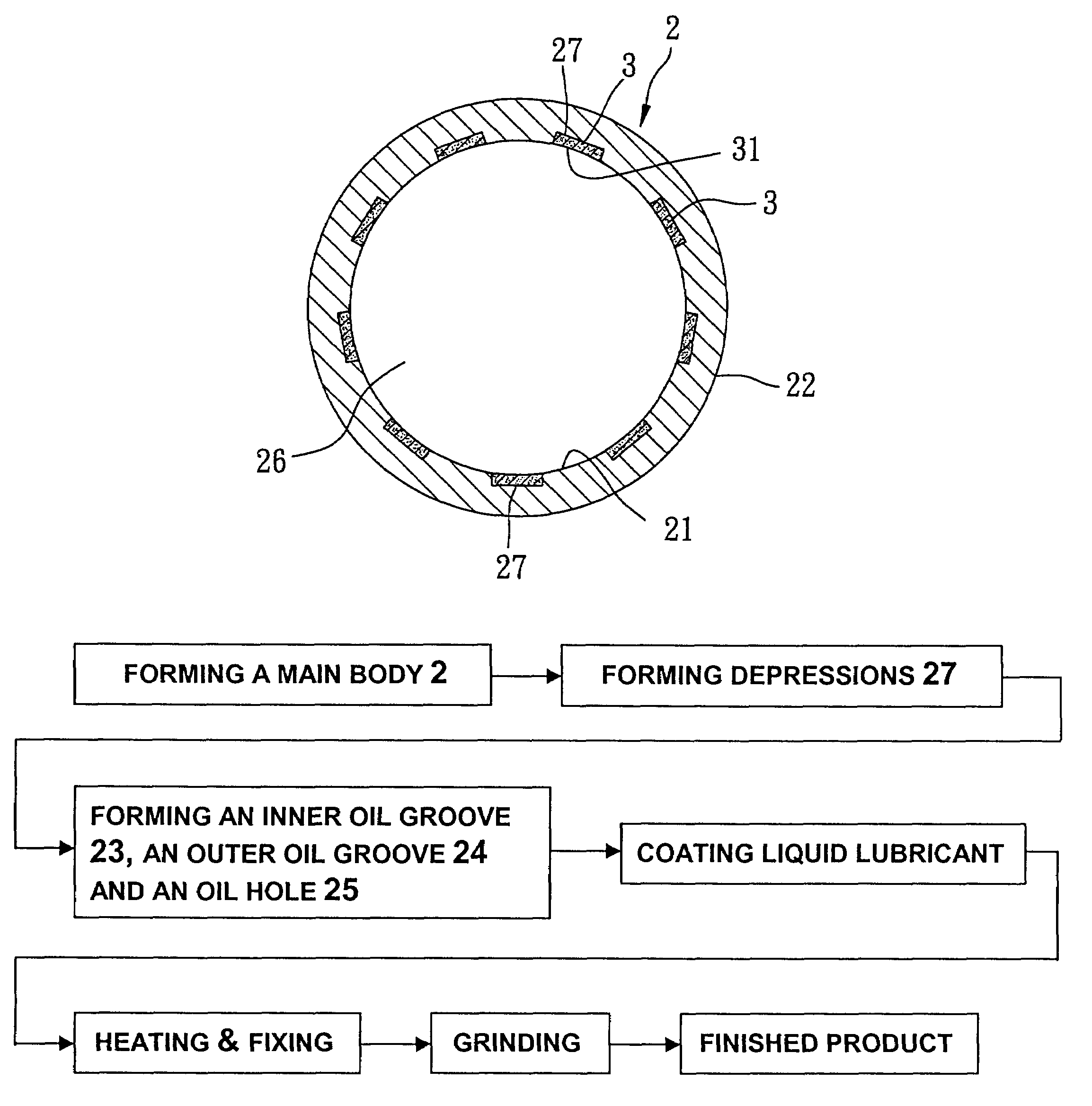
[0029]A preferred embodiment of a self-lubricating bearing in the present invention capable of being sleeved on a relative-moving workpiece 10 in an axial direction, as shown in FIGS. 4 and 5, mainly includes a main body 2 and a plurality of solid lubricant pieces 3 capable of being embedded into the main body 2.

[0030]The main body 2 generally made of copper alloys such as tin bronze, phosphor bronze, etc., or iron or stainless steel has an inner annular wall surface 21 formed around a central axis thereof, an outer annular wall surface 22, an inner oil groove 23 recessed on the inner annular wall surface 21 in an outwardly radial direction, an outer oil groove 24 recessed on the outer annular wall surface 22 in an inwardly radial direction, an oil hole 25 radially penetrating through and communicating with the inner oil groove 23 and the outer oil groove 24, a through hole 26 surrounded and defined by the inner annular wall surface 21 and capable of being sleeved by the relative-m...


PUM

PropertyMeasurementUnit
depthaaaaaaaaaa
depthaaaaaaaaaa
depthaaaaaaaaaa

Abstract

This invention relates to a self-lubricating bearing and a method of producing the same. The self-lubricating bearing includes a main body and a plurality of solid lubricant pieces. The main body has an inner annular wall surface, an outer annular wall surface, and a through hole defined by the inner annular wall surface. The solid lubricant pieces are embedded in a plurality of depressions of the inner annular wall surface by coating and grinding and each has a radial inside annular surface in a curve conforming to that of the inner annular wall surface. The forming of the depressions without radially penetrating through the outer annular wall surface to make the solid lubricant pieces embedded into the depressions with less amount by coating and grinding allows the self-lubricating bearing to reduce the material cost, and keep its structural strength and lubricating effect simultaneously.

Description

BACKGROUND OF THE INVENTION[0001]1. Field of the Invention[0002]This invention relates to a self-lubricating bearing and a method of producing the same, particularly to the self-lubricating bearing having a main body embedded with a plurality of solid lubricant pieces that have wear-resisting and lubricating functions, and the manufacturing method thereof.[0003]2. Description of the Prior Art[0004]Bearings are special objects for decreasing the wearing of components in performing relative motion. There are varied known bearings applied for different situations and designs. A known conventional self-lubricating bearing 1 capable of being sleeved on a relative-moving workpiece 10, as shown in FIGS. 1, 2 and 3, has a metallic main body 11 provided with an inner annular wall surface 111, an outer annular wall surface 112, a plurality of perforated holes 113 radially penetrating through the inner annular wall surface 111 and the outer annular wall surface 112, an outer oil groove 114, an...

Claims


Application Information

Patent Timeline
Patent Type & Authority Patents(United States)
IPC IPC(8): F16C33/04F16C33/14F16C33/10F16C33/24F16C17/02
CPCF16C17/02F16C33/14F16C33/1095F16C33/24Y10T29/49677F16C2220/62F16C2220/70
Inventor LEE, HU I-LONG
Owner LEE HU I LONG
Why Eureka
Try Eureka