Vortex induced vibration suppression device and method

a technology of vibration suppression and vortex, which is applied in mechanical equipment, vessel construction, transportation and packaging, etc., can solve the problems of viv, risers such as those associated with tlp type platforms, and vibration induced vortex

Inactive Publication Date: 2005-05-24
TAQUINO WELDON
View PDF28 Cites 102 Cited by
  • Summary
  • Abstract
  • Description
  • Claims
  • Application Information

AI Technical Summary

Benefits of technology

[0021]The present invention provides an improved method of installing a riser having one or more vortex induced vibration suppression devices thereon. The method includes first making up the riser section on a pipeline lay barge that provides a stinger. The vortex induced vibration device or devices is attached to the pipeline on the lay barge. In this fashion, the riser and attached vortex induced vibration suppression devices can be lowered to the seabed by first passing the riser and attached vortex induced vibration suppression devices over the stinger part of the barge. With the present invention, the improved construction of the vortex induced vibration suppression device enables the apparatus to be lowered over a stinger of a lay barge to the ocean floor.

Problems solved by technology

It has been stated that risers such as those associated with TLP type platforms suffer from vortex induced vibration or “VIV”.
Floatable and tension leg platform (TLP) risers suffer from vibration induced vortex caused by ocean currents, for example.
VIV can be an acute problem in deep water drilling operations.
When these vortices break away from the pipe, they set up vibrations which will dynamically excite the riser and cause the pipe to fail prematurely.
One of the problems of placing a vortex induced vibration suppressor on an oilfield riser pipe such as the riser associated with a deep water oil and gas well drilling or production platform is the problem of installing or placing the strake.
However, such a procedure is dangerous and very costly.
Some VIV devices have multiple parts that limit overall structural strength.

Method used


Image

  • Vortex induced vibration suppression device and method
  • Vortex induced vibration suppression device and method
  • Vortex induced vibration suppression device and method

Examples


Embodiment Construction

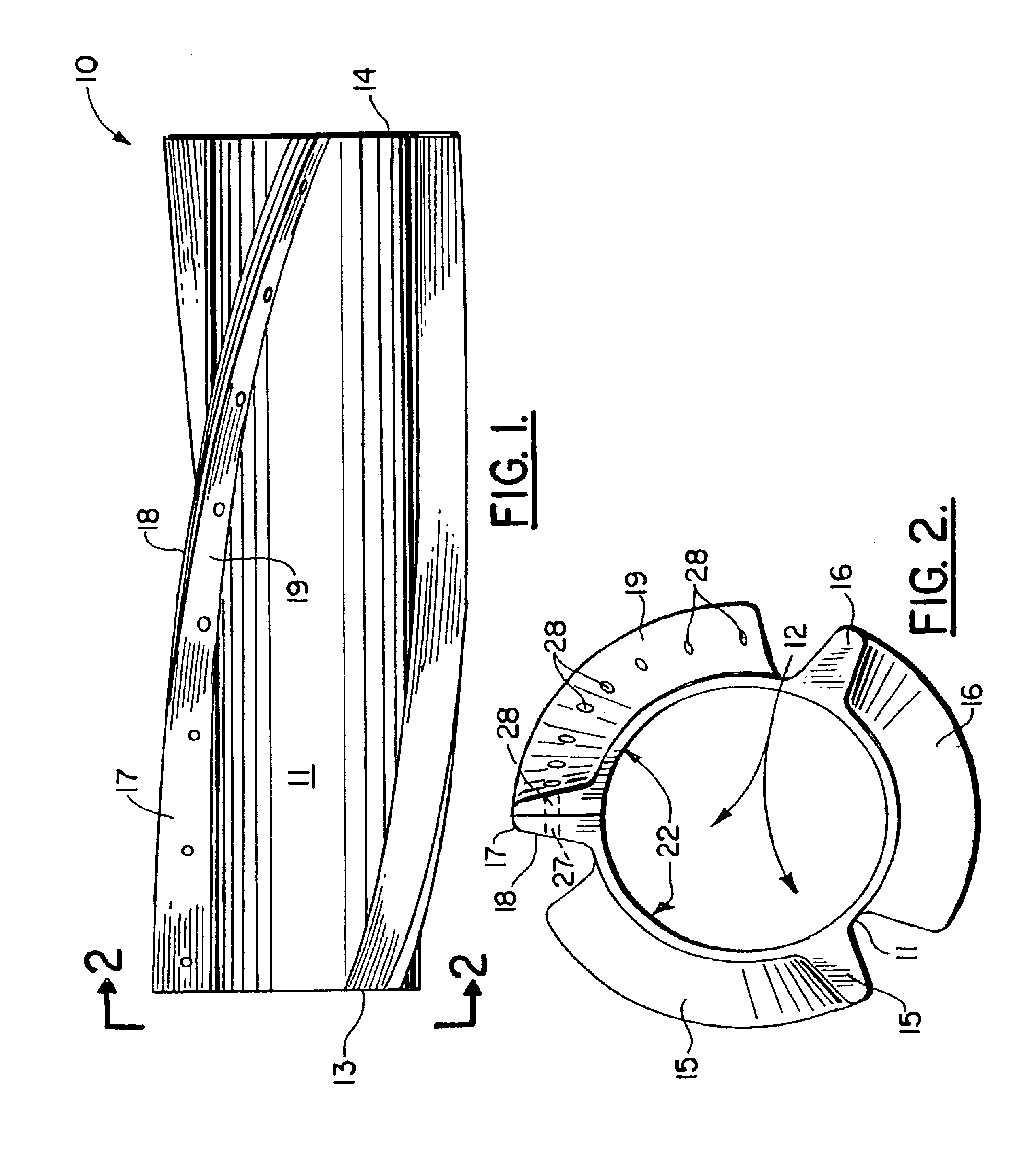
[0039]FIGS. 1-11 show the preferred embodiment of the apparatus of the present invention, designated generally by the numeral 10.

[0040]Vortex induced vibration suppression device 10 includes body 11 having a central longitudinal open ended bore 12 and end portions 13, 14.

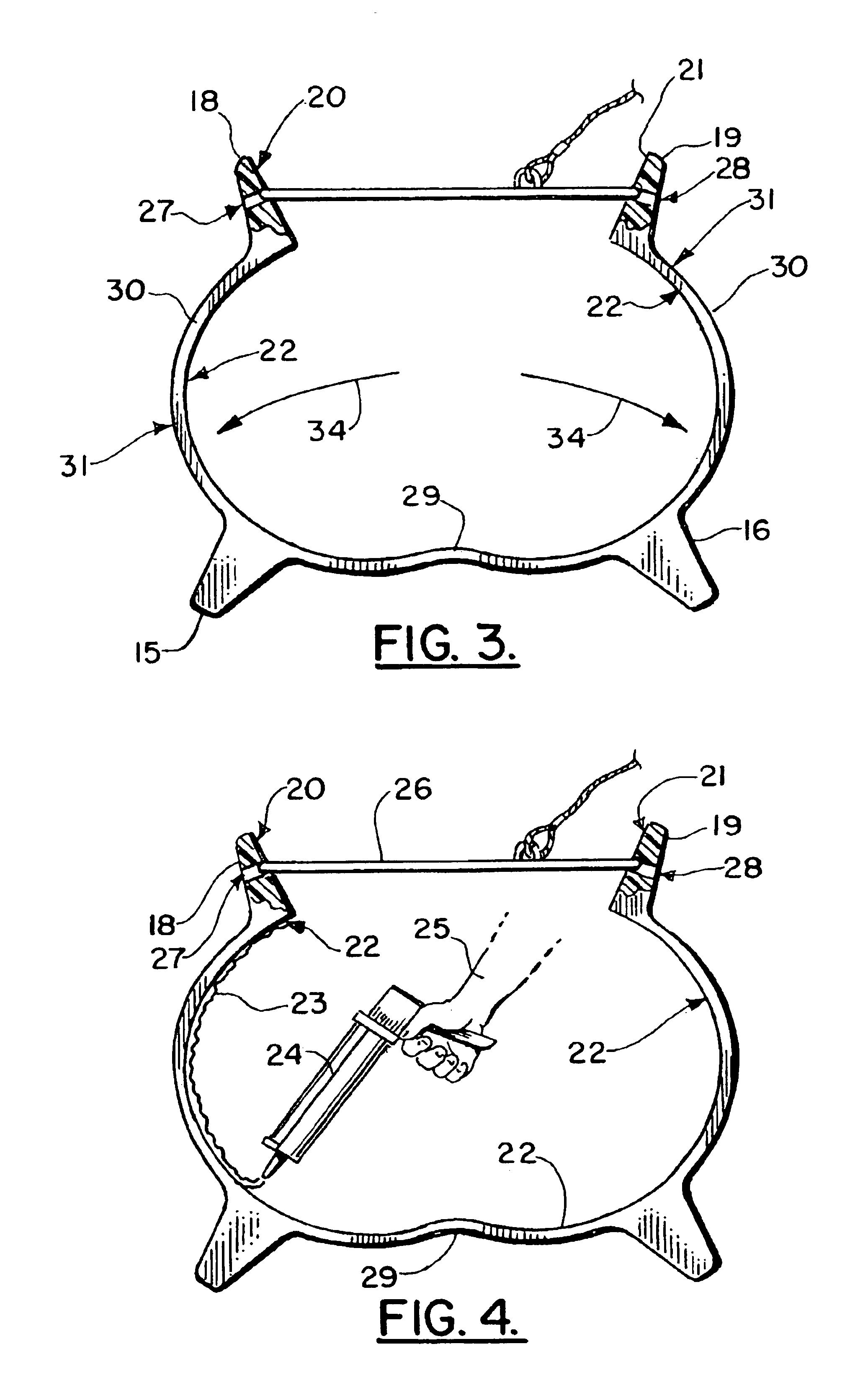
[0041]Body 11 is preferably a one piece, molded or cast flexible body that is preferably of a polymeric material such as polyurethane. A plurality of helical vanes 15, 16, 17 extend from the wall 30 of body 11 and are preferably integral therewith. A longitudinally extending slot can be optionally formed by mating surfaces 20, 21 of vane sections 18, 19 as shown in FIGS. 1-4. Otherwise, body 11 does not have a slot but is a one piece integral member that can be installed by slipping it over an end of a joint of pipe. It can also be case in place on a joint of pipe.

[0042]A hinge area 29 is provided generally opposite vane sections 18, 19 and the respective mating surfaces 20, 21. A user can spread apart the vane sect...


PUM

PropertyMeasurementUnit
flexibleaaaaaaaaaa
lengthaaaaaaaaaa
tensileaaaaaaaaaa

Abstract

A vortex induced vibration suppressor and method is disclosed. The apparatus includes a body that is a flexible member of a polymeric (e.g., polyurethane) construction. A plurality of helical vanes on the body extend longitudinally along and helically about the body. Each vane has one or more openings extending transversely there through. A longitudinal slot enables the body to be spread apart for placing the body upon a riser, pipe or pipeline. Tensile members that encircle the body and pass through the vane openings enable the body to be secured to the pipe, pipeline or riser.

Description

CROSS-REFERENCE TO RELATED APPLICATIONS[0001]This is a continuation-in-part of U.S. Ser. No. 10 / 292,894, filed Nov. 12, 2002, now U.S. Pat. No. 6,695,540 which is a continuation of U.S. patent application Ser. No. 09 / 712,759, filed Nov. 14, 2000 (now abandoned), all hereby incorporated herein by reference.STATEMENT REGARDING FEDERALLY SPONSORED RESEARCH OR DEVELOPMENT[0002]Not applicableREFERENCE TO A “MICROFICHE APPENDIX”[0003]Not applicableBACKGROUND OF THE INVENTION[0004]1. Field of the Invention[0005]The present invention relates to vortex induced vibration suppression and more particularly to an improved apparatus for suppressing vortex induced vibrations in vertical risers of oil and gas well drilling platforms and production platforms. Even more particularly, the present invention relates to an improved vortex induced vibration suppression apparatus, also known as a strake, wherein the improved apparatus includes an elongated body of flexible polymeric material such as polyur...

Claims


Application Information

Patent Timeline
Patent Type & Authority Patents(United States)
IPC IPC(8): E21B17/00E21B17/01F15D1/10F15D1/00
CPCF15D1/10E21B17/01B63B21/50B63B2021/504B63B2231/42F16L1/123
Inventor TAQUINO, WELDON
Owner TAQUINO WELDON
Why Eureka
Try Eureka