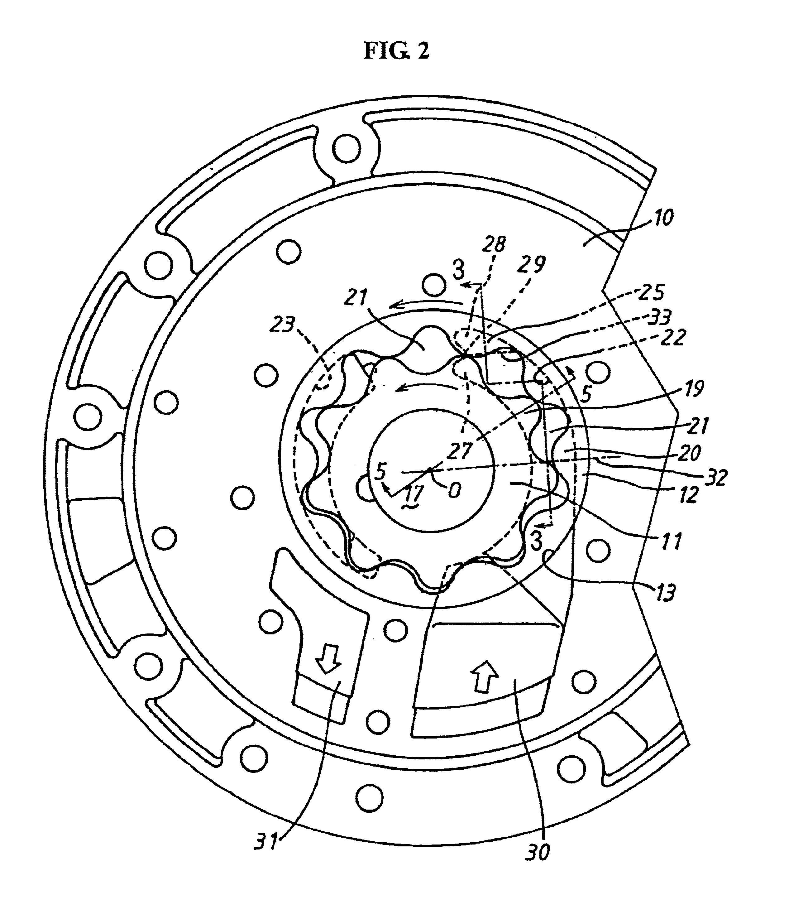
[0008]Accordingly, the gear pump sucks up fluid via an intake port in a region where the individual inter-teeth chambers that are created between the external teeth formed on the outer periphery of the inner rotor and the internal teeth formed on the inner periphery of the outer rotor and meshed with the external teeth expand as rotation of both rotors advances. Further, the gear pump discharges the fluid to the
discharge port in a region where the inter-teeth chambers contract. The bottom portion of the intake port is provided with the sloped bottom surface formed of a plane which is inclined such that the sloped bottom surface approaches the side surfaces of the external teeth and the internal teeth from the upstream side to the downstream side in the rotational direction of both rotors. The fluid that flows in the intake port is regulated by the sloped bottom surface and smoothly guided into the inter-teeth chambers that are expanding. Since the bottom portion of the intake port is provided with the sloped bottom surface formed of a plane free from spiral or twisting, design and manufacturing of the gear pump become extremely easy. Further, the downstream end segment is inclined such that an end of the downstream end segment of the sloped bottom surface which is farther from the
rotational axis of the inner rotor is positioned upstream of an end which is closer thereto. Therefore, the sloped bottom surface is shallower in the outer peripheral side in the radial direction than the inner peripheral side in the radial direction. Therefore, the flow rate in the inner peripheral side in the radial direction increases, and occurrence of
cavitation can be prevented.
[0009]Further, in the aforementioned improved gear pump according to the invention, the sloped bottom surface is connected to a bottom surface adjourning the sloped bottom surface formed of a plane such that an upstream end segment constituting a starting portion of the sloped bottom surface is in parallel with the downstream end segment constituting the end portion of the sloped bottom surface. Therefore, the structure is simplified, the fluid flows smoothly, and design and manufacturing of the gear pump are easy.
[0010]Further, in the aforementioned improved gear pump according to the invention, the upstream end segment constituting the starting portion of the sloped bottom surface formed of a plane is perpendicular to the
rotational axis. Therefore, when the sloped bottom surface is on the elongation line of the inner rotor
radius, the sloped bottom surface is deeper in the inner peripheral side than the outer peripheral side in the radial direction. Accordingly, the fluid flow rate in the inner peripheral side in the radial direction is likely to increase. The thus increased flow rate is offset by urging force of the fluid in the inter-teeth chamber toward the external teeth side due to
centrifugal force. The fluid that flows in the intake port is substantially evenly absorbed into the external teeth side and the internal teeth side of the individual inter-teeth chambers. Accordingly, the pressures in the individual inter-teeth chambers are maintained evenly in the intake region, and occurrence of cavitaion can be prevented.
[0011]Further, in the aforementioned improved gear pump according to the present invention, both the external teeth side and the internal teeth side of the inter-teeth chamber immediately before being blocked from the intake port are closed simultaneously by the downstream edge of the intake port. Accordingly, it is possible to prevent cavitation from occurring due to uneven decrease of the pressure either in the external teeth side or the internal teeth side in the inter-teeth chamber.
[0013]Accordingly, in the inter-teeth chamber immediately before being blocked from the intake port, the fluid that flows in is throttled by the downstream edge of the intake port. Thus, the fluid is urged to the internal teeth side by
centrifugal force of the rotor. However, the fluid inflow from the intake port to the internal teeth side of the inter-teeth chamber is restricted by the shallow bottom flat surface formed in a portion facing the internal teeth of the downstream end portion of the intake port. Therefore, the fluid flow rate from the intake port to the external teeth side of the inter-teeth chamber increases, preventing the pressure in the external teeth side from decreasing. Accordingly, cavitation is reliably prevented.
[0015]Accordingly, the fluid that flows into the internal teeth side of the inter-teeth chamber immediately before being blocked from the intake port is restricted by the shallow bottom flat surface. Further, the fluid flows in from the inner end portion to the external teeth of the inter-teeth chamber. Therefore, it is possible to separate a control of the fluid inflow from the downstream end portion of the intake port to the inter-teeth chamber into a control of the internal teeth side and a control of the external teeth side. Further, the cavitaion that used to occur in the inner side of the external teeth can be prevented more reliably.


