Large area substrate processing system

a processing system and large area technology, applied in the field of large area substrate processing system, can solve the problems of large equipment size and cost, and fabricators seeking to perform a limited number of process steps are disadvantageously required to utilize equipment having capacity, process capability and size, etc., to facilitate the transfer

Inactive Publication Date: 2005-05-24
APPLIED MATERIALS INC
View PDF18 Cites 18 Cited by
  • Summary
  • Abstract
  • Description
  • Claims
  • Application Information

AI Technical Summary

Benefits of technology

[0009]A system and method for processing large area substrates is provided. In one embodiment, a processing system includes a transfer chamber having attached at least one processing chamber and a substrate staging system coupled thereto. The staging system includes a load lock

Problems solved by technology

Conventional systems require large and expensive hardware.
However, this increased equipment size and cost represents a substantial problem for fabricators having limited factory space available for such equipment.
Moreover, fabricators

Method used


Image

  • Large area substrate processing system
  • Large area substrate processing system
  • Large area substrate processing system

Examples


Embodiment Construction

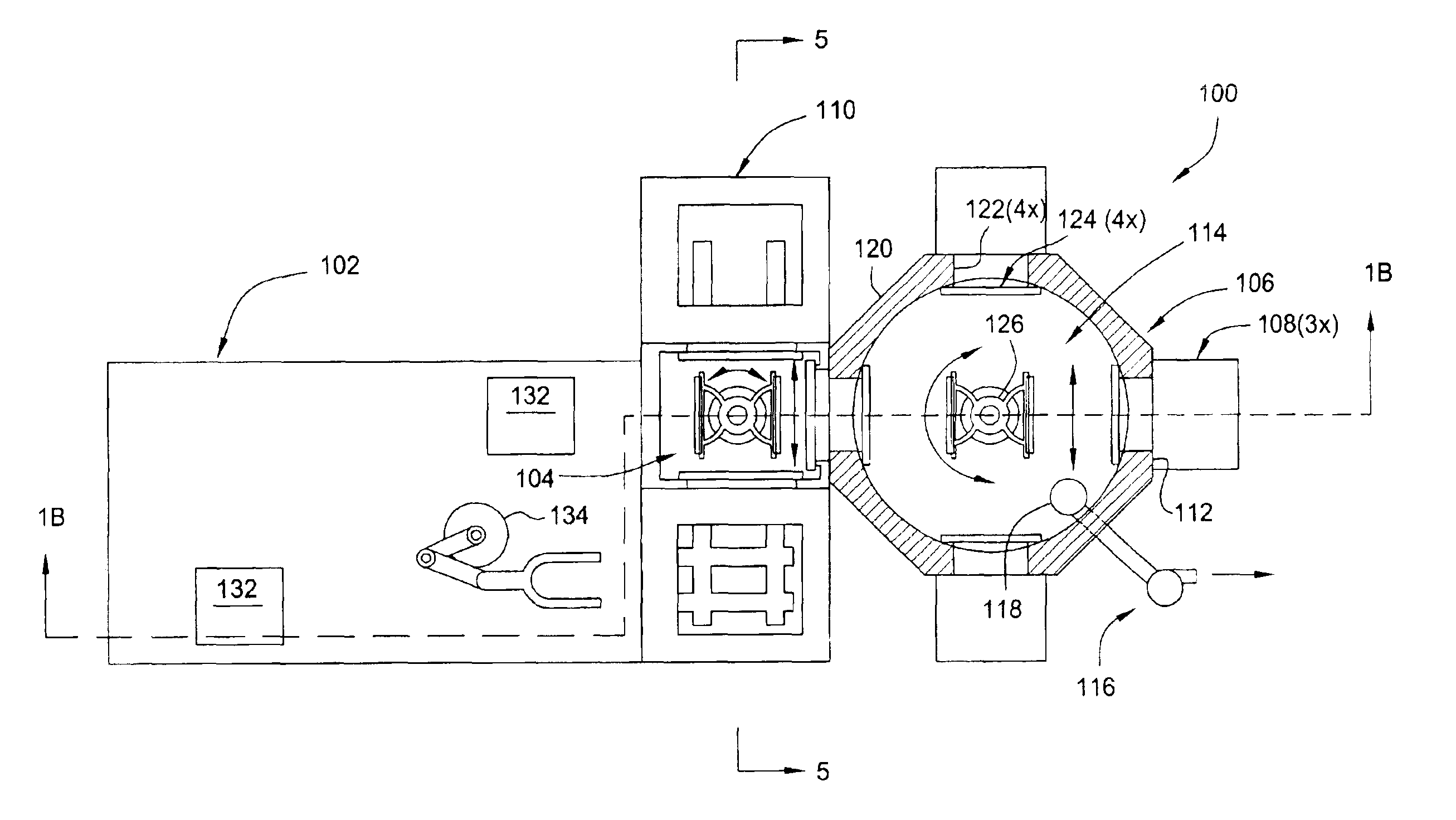
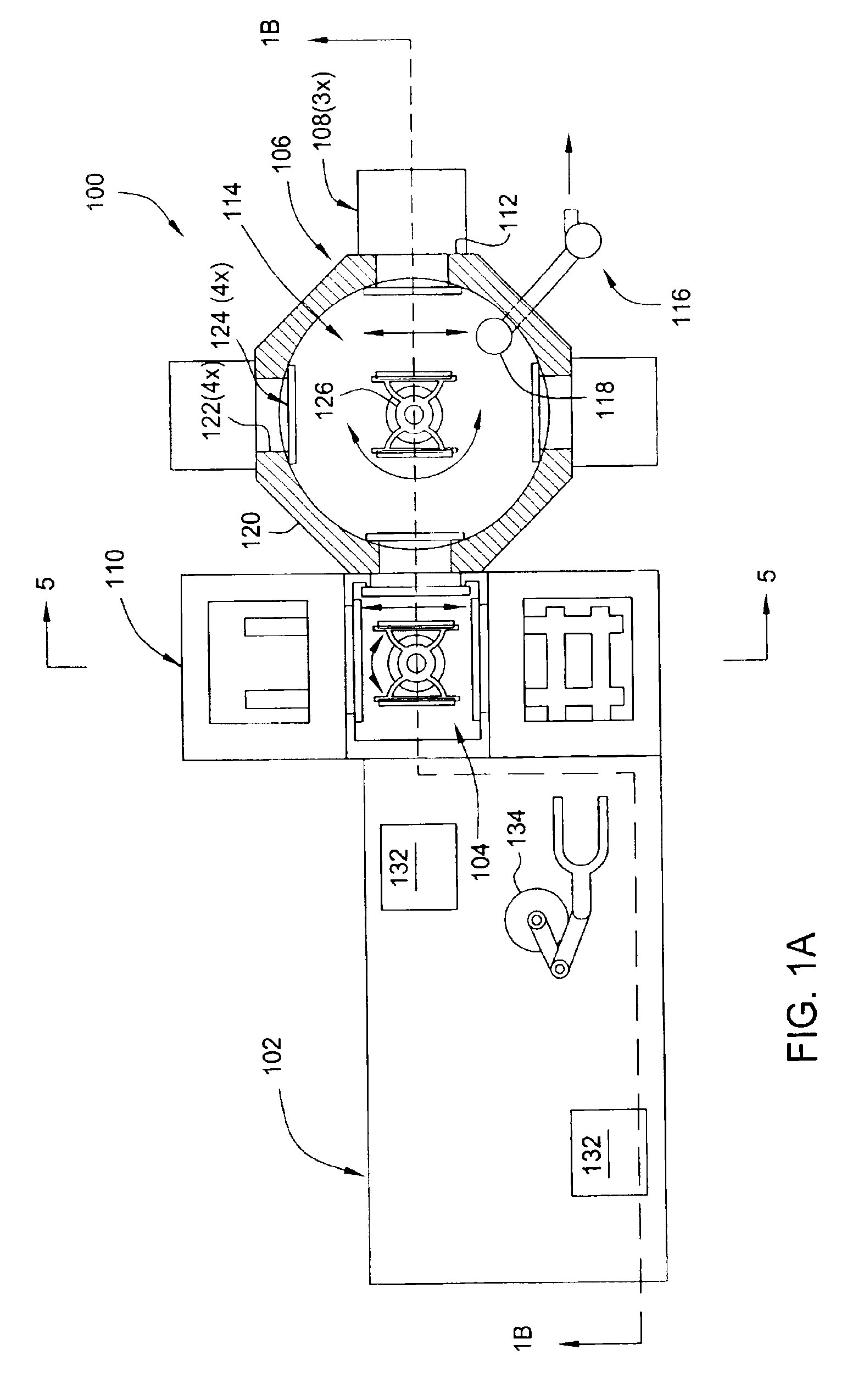
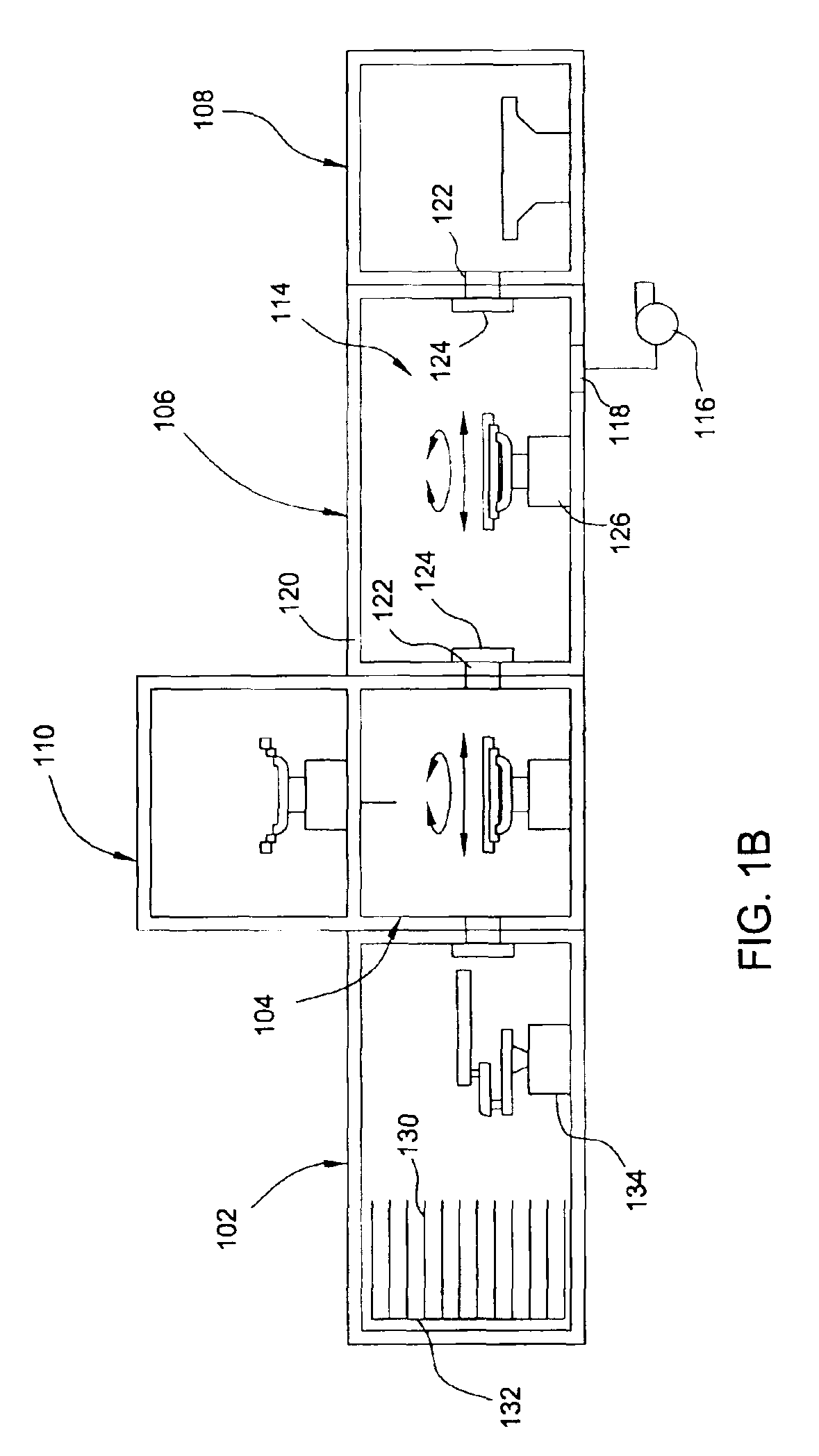
[0022]FIGS. 1A-B is a top plan view and a sectional view of one embodiment of a large area substrate processing system 100. The processing system includes a factory interface 102 coupled by a load lock chamber 104 to a transfer chamber 106 that has at least one processing chamber 108 coupled thereto. The load lock chamber is part of a staging system 110 adapted to queue and / or thermally treat or otherwise condition substrates being transferred between the factory interface 102 and the transfer chamber 106. The factory interface 102 has any number of configurations, and typically includes at least one substrate storage cassette 132 and an interface transfer robot 134 for transferring substrates 130 between the cassettes 132 and the staging system 110.

[0023]The transfer chamber 106 has a chamber body 120 that is typically fabricated from a suitable material such as aluminum, stainless steel, or polypropylene. The transfer chamber may be rectangular or circular cross-section as depicte...


PUM

PropertyMeasurementUnit
Temperatureaaaaaaaaaa

Abstract

A system and method for processing large area substrates is provided. In one embodiment, a processing system includes a transfer chamber having at least one processing chamber and a substrate staging system coupled thereto. The staging system includes a load lock chamber having a first port coupled to the transfer chamber and a heat treating station coupled to a second port of the load lock chamber. A load lock robot is disposed in the load lock chamber to facilitate transfer between the heat treating station and the load lock chamber.

Description

BACKGROUND OF THE INVENTION[0001]1. Field of the Invention[0002]Embodiments of the present invention generally relate to a large area substrate processing system having a transfer robot.[0003]2. Description of the Related Art[0004]Thin film transistors (TFT) are commonly used for active matrix displays such as computer and television monitors, cell phone displays, personal digital assistants (PDAs), and an increasing number of other devices. Generally, flat panels comprise two glass plates having a layer of liquid crystal materials sandwiched therebetween. At least one of the glass plates includes one conductive film disposed thereon that is coupled to a power source. Power, supplied to the conductive film from the power source, changes the orientation of the crystal material, creating a pattern display.[0005]With the marketplace's acceptance of flat panel technology, the demand for larger displays, increased production and lower manufacturing costs have driven equipment manufacture...

Claims


Application Information

Patent Timeline
IPC IPC(8): F27B13/00F27D3/00H01L21/00B65G49/06H01L21/02H01L21/677H01L21/68
CPCH01L21/67742H01L21/67748H01L21/67109H01L21/67115Y10S414/14Y10S414/137Y10S414/135H01L21/02H01L21/68
Inventor BACHRACH, ROBERT Z.BLONIGAN, WENDELL T.
Owner APPLIED MATERIALS INC
Why Eureka
Try Eureka