Stent

Inactive Publication Date: 2005-05-24
BIOTRONIK MESTRASSE UND THERAPIEGERATE GMBH & CO ING BERLIN
14 Cites 139 Cited by

AI-Extracted Technical Summary

Problems solved by technology

The advantage of the closed structure in terms of covering the inside wall of the vessel is however at the cost of the disadvantage that those stents involve relative longitudinal stiffness during insertion of the stent in particular into narrow blood vessels.
Those stents therefore do not make it possible in the optimum fashion for the stent to be introduced through possibly very sharply curved vessel portions of the coronary blood vessels, upon being introduced in a direction towards the stenosis to be treated.
Closed structures also give rise to problems in regard to using them in the region of curved vessel portions, by virtue of their longitudinal stiffness.
A particular disadvantage with a closed structure like the wall stent moreover is that substantial longitud...

Method used

[0048]The tubular portions 8 are connected together by way of first connecting webs or bars 20 serving as first connecting means. The first connecting bars 20 extend substantially parallel to the longitudinal axis of the stent 1. It will be appreciated however that, in other variants of the invention, the first connecting bars can also be of a different configuration and/or arrangement. In particular, the first connecting bars may also in known fashion involve a configuration which contributes to enhancing the flexibility of the stent. Thus, the first connecting bar in question may for example also extend in an S-shape.
[0050]FIG. 2 is a diagrammatic view of the stent 1 of FIG. 1 in a non-expanded condition (dotted lines) and an expanded condition (bold lines). Parts which correspond to parts in FIG. 1 are denoted in FIG. 2 by the same references. In addition, also shown in FIG. 2 are elliptical areas 26 and 28 which correspond to the free areas 26 and 28 of an expanded stent 32 from the state of the art, as shown in FIGS. 3 and 4. FIG. 2 clearly shows that the free areas 26 and 28 present in FIG. 4 in the expanded condition of a stent 1 according to the invention are no longer present in the same size, thus affording an improvement in the coverage of the inside of a vessel.
[0057]As is already the case with the embodiment shown in FIG. 1, the elements 10′ of each tubular portion 8′ in this variant are also so arranged in mutually displaced relationship in the longitudinal direction of the stent 1′ that their ends define the described edge contours 37 and 38 which extend around the stent in a wave-like configuration with respect to the peripheral direction of the stent in in-phase relationship. Furthermore, in this case also the tubular portions 8′ are so arranged relative to each other that mutually adjacent edge contours 36 and 37 of adjacent portions 8′ extend in phase with each other, whereby in accordance with the invention particularly good and uniform coverage of the inside wall of th...

Benefits of technology

[0009]Therefore the object of the present invention is further to develop a stent of the kind set forth in the opening part of this specification, in such a way that the above-menti...

Abstract

A stent, in particular a coronary stent, comprising at least two tubular portions which are arranged adjacently in the longitudinal direction of the stent and which comprise a plurality of interconnected, substantially cell-shaped elements which have an orientation and are connected together in the longitudinal direction of the stent by way of at least one first connecting means, wherein the elements are of such an arrangement and/or configuration that the ends of the elements which are in the longitudinal direction of the stent define an edge contour extending around the stent in a wave-like configuration in the peripheral direction thereof, and wherein the mutually adjoining edge contours of two tubular portions extend around the stent substantially in in-phase relationship.

Application Domain

Technology Topic

Cell shapePhase relationship +2

Image

  • Stent
  • Stent
  • Stent

Examples

  • Experimental program(1)

Example

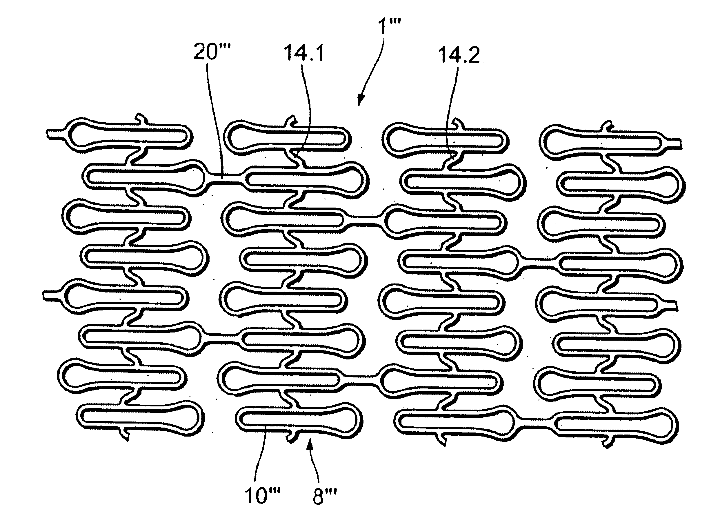
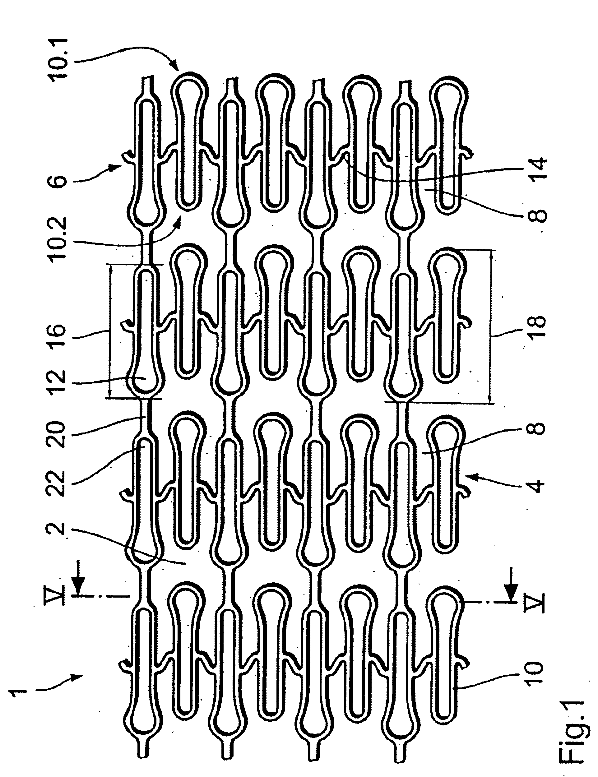
[0045]FIG. 1 shows a stent 1 according to the invention. The stent 1 is shown in FIG. 1 in a form of a part of the development of its peripheral surface 2. In the condition of the stent 1 in which it is ready for operation, the peripheral surface 2 is connected with its side 4 which is shown at the bottom in FIG. 1 to the side 6 which is shown at the top in FIG. 1, thus affording the tubular stent 1 in the configuration in which it is ready for operation.
[0046]The peripheral surface 2 is composed of four tubular portions 8 which are also shown as a development in FIG. 1. In FIG. 1, each tubular portion 8 has eight cell-shaped elements 10 which are asymmetrical in the form of a keyhole and which have an orientation. In each tubular portion 8 the cell-shaped elements 10 are respectively arranged adjacent to each other in the peripheral direction of the stent, oriented with their longitudinal axes parallel to the longitudinal axis of the stent 1. Each element 10 involves an identical basic shape. The elements 10 however are arranged in such a way that the keyhole-like basic shape of the elements 10 respectively involves an opposite orientation in adjacent elements 10, that is to say the outwardly bulging ends 12 of the elements 10 are respectively turned through 180° relative to each other, in adjacent elements 10.
[0047]The elements 10 which are adjacent in the peripheral direction of the stent are connected together in the peripheral direction of the stent 1 by way of S-shaped second connecting webs or bars 14 serving as second connecting means, and aligned coaxially in the longitudinal direction of the stent. The S-shaped second connecting bars 14 provide that adjacent elements 10 are each displaced a little relative to each other in the longitudinal direction of the stent 1. The length 16 of the elements 10 of each tubular portion 8 is therefore respectively less than the width 18 of each tubular portion 8. Accordingly therefore the ends 10.1 and 10.2 respectively of the elements 10, which are disposed in the longitudinal direction of the stent 1, define for each tubular portion 8 two edge contours which extend around the stent 1 in the peripheral direction thereof in a wave-like configuration in in-phase relationship with each other. In this case the tubular portions 8 are also arranged in such a way that the mutually adjoining edge contours of adjacent tubular portions 8 extend around the stent in in-phase relationship.
[0048]The tubular portions 8 are connected together by way of first connecting webs or bars 20 serving as first connecting means. The first connecting bars 20 extend substantially parallel to the longitudinal axis of the stent 1. It will be appreciated however that, in other variants of the invention, the first connecting bars can also be of a different configuration and/or arrangement. In particular, the first connecting bars may also in known fashion involve a configuration which contributes to enhancing the flexibility of the stent. Thus, the first connecting bar in question may for example also extend in an S-shape.
[0049]The first connecting bars 20 connect respectively adjacent elements 10 of the portions 8 together, insofar as they connect the outwardly bulging end 12 of an element 10 to the narrow end 22 of an element 10. As shown in FIG. 1, each second element 10 of a tubular portion 8 is connected to the element 10, which is respectively adjacent in the longitudinal direction of the stent 1, of the adjacent tubular portion 8. All elements 10 which are connected by way of a first connecting bar 20 to an adjacent element 10 are also always connected on the respective other side to a further element 10 of the portion 8 which is adjacent on that side, so that all first connecting bars 20 are aligned with each other as viewed in the longitudinal direction. That excludes the elements 10 which are not shown in FIG. 1 and which are arranged at the ends of the stent and which do not have any further first connecting bars 20 towards the edge.
[0050]FIG. 2 is a diagrammatic view of the stent 1 of FIG. 1 in a non-expanded condition (dotted lines) and an expanded condition (bold lines). Parts which correspond to parts in FIG. 1 are denoted in FIG. 2 by the same references. In addition, also shown in FIG. 2 are elliptical areas 26 and 28 which correspond to the free areas 26 and 28 of an expanded stent 32 from the state of the art, as shown in FIGS. 3 and 4. FIG. 2 clearly shows that the free areas 26 and 28 present in FIG. 4 in the expanded condition of a stent 1 according to the invention are no longer present in the same size, thus affording an improvement in the coverage of the inside of a vessel.
[0051]FIG. 3 shows a stent from the state of the art. In this case also—in order to make it easier to compare the invention to the state of the art—parts which in substance correspond to those of the stent 1 in FIG. 1 are denoted by the same references. It will be seen from FIG. 3 that, in the state of the art, respective elements 10 of opposite orientation were connected by way of the connecting means 20. In that way, a connection was made between the narrow ends 22 of the respective elements 10 by means of the respective connecting bar 20. In the state of the art that again resulted in the free areas 26 and 28 shown in FIG. 4.
[0052]FIG. 5 shows a highly diagrammatic view in cross-section through the stent 1, not in the expanded or developed state, in the region of the line V—V in FIG. 1, in which each tubular portion has eight elements 10. Of those eight elements 10, each second one is connected by way of connecting bars 20 to elements of an adjacent tubular portion. Overall therefore, as indicated by the larger spots 20, four elements 10 are connected by way of connecting bars 20 to elements of the adjacent portion, thus affording a four-figure axis of symmetry 38 of the tubular portions.
[0053]FIG. 6 shows an also highly diagrammatic projection of two adjacent tubular portions of a further stent 1′ according to the invention. In this case the tubular portions 8 correspond to the portions shown in FIG. 5. However they are turned relative to each other through 45° or half a period of the peripherally extending edge contours of the portions. In this case also the larger spots 20′ symbolically represent the elements 10′ connected to connecting bars 20′.
[0054]As already mentioned, FIGS. 5 and 6 are highly diagrammatic views. The illustrated contours are only indicative place-markers for the sectioned parts of the stent in question and do not reproduce the actual section contour thereof.
[0055]FIG. 7 shows a further preferred embodiment of the stent 1′ according to the invention with eight elements 10′ per tubular portion 8′. This embodiment is the same in terms of its fundamental structure as that shown in FIG. 1 so that only the differences will be discussed in detail here.
[0056]The difference is that there are only two respective connecting bars 20′ between each two adjacent tubular portions 8′ of the stent 1′, wherein at each fourth element 10′ a connecting bar engages the tubular portion 8′ which adjoins it in a first direction. The connecting bars 20′ are further displaced from one portion 8′ to another portion 8′ by half a period of the wave-like edge contour of the portions 8′, as is indicated by the broken-line contours 36 through 38. That displaced arrangement of the connecting bars 20′ affords a stent which is flexible over its length in all directions in space.
[0057]As is already the case with the embodiment shown in FIG. 1, the elements 10′ of each tubular portion 8′ in this variant are also so arranged in mutually displaced relationship in the longitudinal direction of the stent 1′ that their ends define the described edge contours 37 and 38 which extend around the stent in a wave-like configuration with respect to the peripheral direction of the stent in in-phase relationship. Furthermore, in this case also the tubular portions 8′ are so arranged relative to each other that mutually adjacent edge contours 36 and 37 of adjacent portions 8′ extend in phase with each other, whereby in accordance with the invention particularly good and uniform coverage of the inside wall of the vessel is achieved in the expanded condition.
[0058]FIG. 8 shows a further preferred embodiment of the stent 1″ according to the invention, with eight elements 10″ per tubular portion 8″. This embodiment is the same in terms of its fundamental structure to that shown in FIG. 1 so that only the differences will be discussed here.
[0059]One difference is that there is only one respective connecting bar 20″ between each two adjacent tubular portions 8″ of the stent 1″. The connecting bars 20″ are further displaced from one portion 8″ to another portion 8″ by one and a half periods of the wave-like edge contour of the portions 8″, as is indicated by the broken-line contours 36″ through 38″. The small number and the displaced arrangement of the connecting bars 20″ affords a stent which is extremely flexible over its length in all directions in space.
[0060]A further difference is that the spacing in the longitudinal direction between the tubular portions 8″ is selected to be so small that the edge contours 36″ and 37″ of adjacent tubular portions 8″ engage into each other in the manner of a tooth configuration. In this case, in other words, the individual elements 10″ of the one tubular portion 8″ come so close to the elements 10″ of the adjacent tubular portion 8″ that the adjacent elements 10″ partially overlap in the longitudinal direction of the stent 1″. This configuration affords particularly small uniform gaps in the expanded stent structure and thus provides for extremely good coverage of the inside wall of the vessel.
[0061]FIG. 9 shows another preferred variant of the stent 1′″ according to the invention, which differs from the variant shown in FIG. 7 only in that second connecting bars 14.1 and 14.2, which face in the same peripheral direction, of elements 10′″ which are mutually adjoining in the longitudinal direction of the stent 1′″ are arranged inclinedly in opposite relationship with respect to the peripheral direction. Together with the arrangement of the first connecting bars 20′″, which has already been described with reference to FIG. 1 and which is displaced by half a period of the edge contours, the FIG. 9 configuration provides for good compensation in respect of the reduction in length of the stent upon expansion thereof.
[0062]That results from the longitudinal displacement of the individual elements 10′″, which occurs upon expansion and which in turn results from the orientation of the second connecting bars 14′″ in the peripheral direction of the stent 1′″. That longitudinal displacement is added up by virtue of the illustrated configuration over the entire stent, whereby the reduction in length of the stent, which is caused by the reduction in length of the individual elements 10′″ upon expansion of the stent, can be reduced to a minimum and possibly even to zero.
[0063]FIG. 10 shows a highly diagrammatic development of the peripheral surface of a further preferred embodiment of the stent 1″″ according to the invention, with elements 10″″ forming the tubular portions 8″″, this arrangement having two different types of elements 10.3 and 10.4. In this case the elements 10.3 and 10.4 are not shown in their actual configuration but are only represented by cells of different sizes. In this case, the elements 10.3 and 10.4 can differ both in respect of their configuration and also only in respect of their dimensions.
[0064]The essential difference in this variant in relation to the above-described embodiments of the invention is the fact that, in this embodiment, by virtue of the different dimensions of the elements 10.3 and 10.4 in the longitudinal direction of the stent 1″″, the tubular portions 8″″ have edge contours 37″″ and 38″″ which extend around the stent in a wave-like configuration and which are displaced relative to each other by half a period. The center points of the elements 10.3 and 10.4, being given with respect to the longitudinal direction of the stent 1″″, are arranged in mutual alignment in the peripheral direction of the stent so that the edge contours 37″″ and 38″″ extend therearound with the same amplitude.
[0065]Otherwise, this structure also again embodies the configuration according to the invention in which the adjacent edge contours 36″″ and 37″″ of two tubular portions 8″″ extend around the stent in in-phase relationship with each other. Likewise, in this case also once again the structure involves the first connecting bars 20″″ being arranged in displaced relationship by half a period of the edge contours. The second connecting bars 14″″ are only diagrammatically shown in FIG. 10. It will be appreciated that they can be of the same arrangement and/or configuration as described above in relation to the foregoing examples. In particular, in this case also a suitable compensation for the reduction in length of the stent can again be achieved in a similar manner to the configuration already described above.
[0066]To sum up, it can be noted that this design configuration also makes it possible to achieve the same advantages as the above-described variants.
[0067]FIGS. 11a through 11d show various forms of elements 10, as can be used in mutually adjacent relationship in the tubular portions in the stents according to the invention as shown in foregoing FIGS. 1 and 7 through 10—in particular in the stent shown in FIG. 10—in place of the elements 10 through 10″″ illustrated there.
[0068]The embodiments of FIGS. 11a and 11b involve a completely closed structure while the embodiments of FIGS. 11c and 11d have two outer bars 40 and 50 which in themselves do not afford a closed structure but which by virtue of a connecting bar 60 also form closed element areas or a closed cell-shaped unit.
[0069]The stents according to the invention have been described hereinbefore by means of examples with edge contours which extend in an approximately sinusoidal configuration. It will be appreciated however that in other variants of the invention it is also possible to use other configurations with edge contours which extend around the stent in a less uniformly wave-like configuration. In particular the arrangement of the elements forming the tubular portions does not necessarily have to be respectively alternate. The elements can for example also be arranged in groups which are disposed alternately in mutually displaced relationship in accordance with the examples shown in FIGS. 1 and 7 through 9 and which in addition or alternatively may involve different dimensions in the longitudinal direction of the stent in accordance with the example shown in FIG. 10. In that respect the groups may also contain a different number of elements and additionally or alternatively also include different kinds of elements.

PUM

no PUM

Description & Claims & Application Information

We can also present the details of the Description, Claims and Application information to help users get a comprehensive understanding of the technical details of the patent, such as background art, summary of invention, brief description of drawings, description of embodiments, and other original content. On the other hand, users can also determine the specific scope of protection of the technology through the list of claims; as well as understand the changes in the life cycle of the technology with the presentation of the patent timeline. Login to view more.

Similar technology patents

Imaging lens and imaging apparatus

Owner:NANCHANG O FILM OPTICAL ELECTRONICS TECH CO LTD

Classification and recommendation of technical efficacy words

  • Reduce in size
  • Avoids disadvantage

Method and system for generation and playback of supplemented videos

ActiveUS20090276805A1Reduce in sizeGood targetTelevision system detailsMultimedia data queryingAggregate dataObject based
Owner:AIBUY INC

Exercise Device

Owner:LAMORE GEORGE

People also interested in

Why Eureka
Try Eureka