Switch gear and method of manufacturing thereof

a technology of switch gear and manufacturing method, which is applied in the direction of switch gear arrangement, contact mechanism, resin casing arrangement, etc., can solve the problems of wasting a great deal of time in ensuring accurate dimensions during assembly, and achieve the effect of increasing the cooling area of the surface of the molded produ

Inactive Publication Date: 2005-05-24
KK TOSHIBA
View PDF10 Cites 38 Cited by
  • Summary
  • Abstract
  • Description
  • Claims
  • Application Information

AI Technical Summary

Benefits of technology

[0010]Accordingly, one object of the present invention, which has been designed in response to the abovementioned problems, is to provide a novel switch gear and method of manufacturing the same which is both economical and efficient by virtue of the fact that the whole device is molded en bloc at high speed, thus reducing both the number of parts and the number of man hours required for molding. In the present invention, this is achieved thanks to the solid insulation of vacuum valves having among other functions those of vacuum circuit breaker and vacuum disconnector, thus providing a degree of dielectric strength which surpasses that of SF6 gas insulation, while at the same time rendering the whole device more compact.

Problems solved by technology

Failure to do so may lead to serious problems resulting from divergent timing and uneven contact when the contacts within the vacuum valves are switched.
As a result, a great deal of time is wasted on ensuring accurate dimensions during assembly.

Method used


Image

  • Switch gear and method of manufacturing thereof
  • Switch gear and method of manufacturing thereof
  • Switch gear and method of manufacturing thereof

Examples


first embodiment

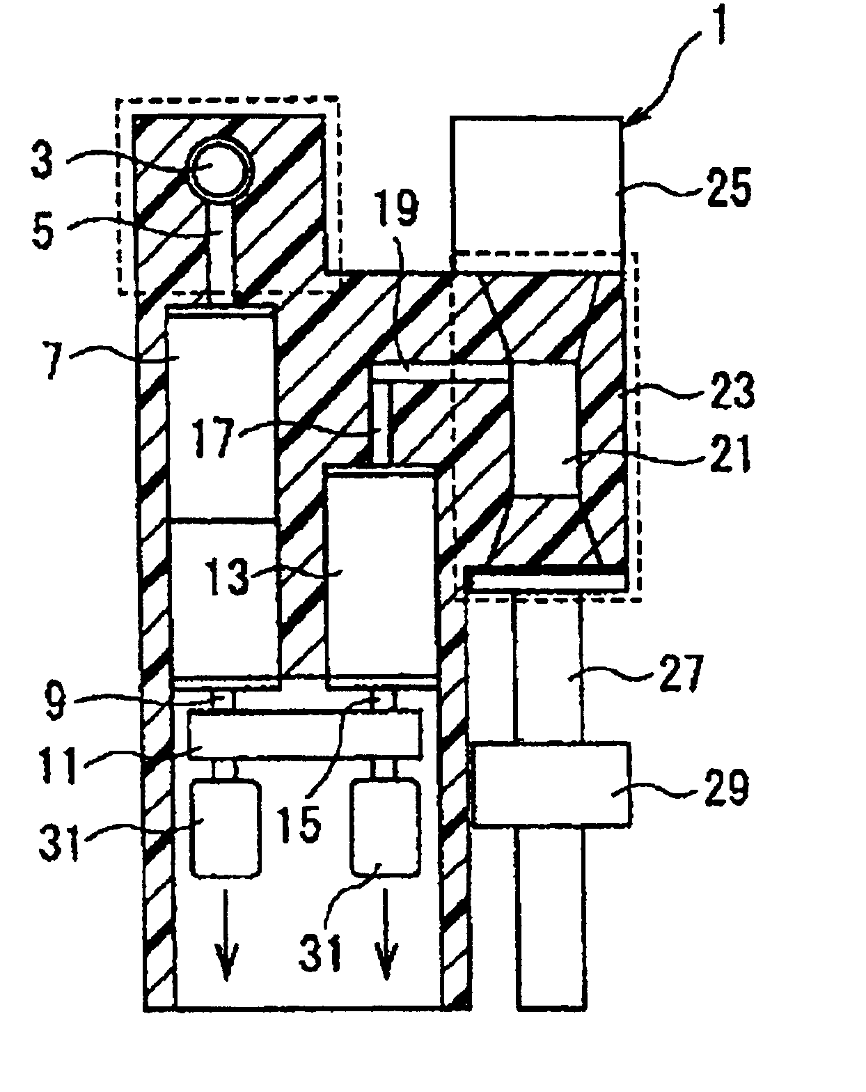
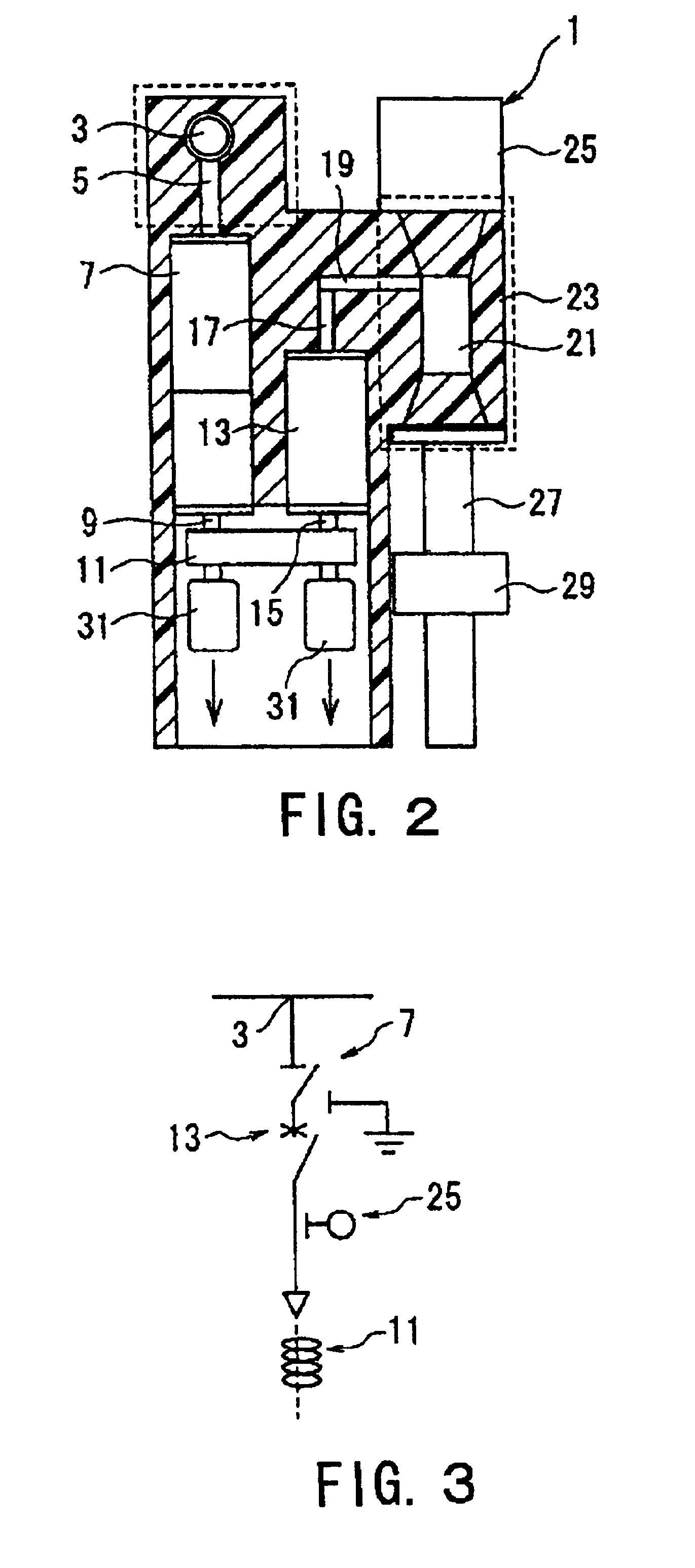
[0077]FIG. 2 is a cross-sectional drawing of the principal section of a switch gear illustrating the present invention, and FIG. 3 is a one-line diagram of a switch gear. FIG. 2 shows a cross-section of one phase of a switch gear 1. From the bus-line connecting member 3 a fixed conductor forming an electrode divides into a T-shape junction and connects to a vacuum disconnector 7 having an earth function. A movable-side conductor 9 which forms the electrode of the vacuum valve which constitutes the vacuum disconnector 7 connects by way of a multi-contact band or other connecting member 11 to a movable-side conductor 15 which forms the electrode of a vacuum valve 13 which constitutes a vacuum circuit breaker. A fixed conductor 17 of the vacuum valve 13 connects by way of a conductor 19 to a T-junction cable head receptor 21.

[0078]With a connection established from the bus-line (generating line) connecting member 3 to the cable head receptor 21, a single molded product is obtained by i...

second embodiment

[0084]There follows a description of a second embodiment with reference to FIGS. 7-12.

[0085]FIG. 7 is a top view of a three-phase configuration of the switch gear 1, while FIG. 8 is a frontal view of FIG. 7 seen from the direction of the arrow. The respective input members (bus-line connecting members) 3 of the molded switch gears 1 are arranged in such a manner that the bus-lines 51 do not overlap one another in the vertical direction. In this case, a separate metal mold is used to form area A in FIG. 8 for each phase in addition to the main metal mold which is used to form the vacuum valves 7 and 13 and other elements which make up the main body of the switch gear 1 as in the first embodiment. In the mold, the length connecting the vacuum valve 7 within the main body and the fixed conductor 5 of the bus-line connecting member 3 are altered in accordance with the type of bus-line connecting member 3. Thus, by changing the metal mold of the bus-line connecting member 3 it is possibl...

third embodiment

[0088]FIGS. 13-16 illustrate the present invention.

[0089]The third embodiment concerns the end shape of the vacuum valves 3 and 17 made of ceramic material as in FIGS. 4 and 5 when they are molded en bloc. FIG. 13 is an outline cross-sectional view illustrating a vacuum valve 7 or 13 which is to be molded en bloc (the interior of the insulation tube has been omitted). To a ceramic insulation tube 59 is sealed and attached within a vacuum a movable side endplate 67, to which in turn are attached a fixed side endplate 63 with fixed conductor 61, a movable side conductor 65 and bellows, which are not illustrated in the drawing. This forms the vacuum valve 7 or 13, to both ends of which are attached metal caps 69 made of copper or a similar metallic material. FIG. 14 is an outline drawing of a the metal cap 69. By assembling vacuum valves 7 and 13 with attached metal caps 69 of this sort and molding them en bloc with particulate epoxy molding material in which elastomer particles have b...


PUM


Abstract

By molding a plurality of vacuum valves (7), (13) having differing functions together with an input member (3) and an output member (21) en bloc in a resin layer (23) to form a switch gear (1), the present invention seeks to achieve dielectric strength without resorting to the use of SF6 gas, while rendering the whole device more compact and reducing both the number of parts and the man hours required for molding.

Description

BACKGROUND TO THE INVENTION[0001]1. Field of the Invention[0002]The present invention relates to a switch gear, and more particularly to a switch gear comprising a vacuum circuit breaker, vacuum disconnector or similar vacuum switch used for interruption and continuity or switching in electric power and reception and / or distribution systems.[0003]2. Description of the Related Art[0004]FIG. 1 illustrates an example of the configuration of a typical switch gear as used in electric power and reception and / or distribution systems. In FIG. 1, a receptacle 101 is surrounded with mild steel plating and divided internally with a partition 103. A circuit breaker chamber 105 at the front houses a circuit breaker 109 fitted with a vacuum valve 107, while a bus-line chamber 111 at the rear is equipped with identical disconnectors 113 and 114 corresponding to upper and lower main circuits on the circuit breaker 109 side. The upper disconnector 113 side is connected to a bus-line 117 which is fix...

Claims


Application Information

Patent Timeline
Patent Type & Authority Patents(United States)
IPC IPC(8): H02B13/00H02B13/01H02B13/035H01H33/66H01H31/00H02B13/02H01H11/00H01H33/02H02B1/56
CPCH02B13/0354H02B1/56H02B13/01H01H11/0031H01H31/003H01H33/027H01H33/66H01H2009/523H01H2033/6613H01H2033/6623H01H2033/566
Inventor ITO, YOSHIHIROKINOSHITA, SUSUMUMAKISHIMA, SATOSHISEKIYA, HIROKIMIYAGAWA, MASARUSHIMIZU, TOSHIO
Owner KK TOSHIBA
Why Eureka
Try Eureka