
Method and apparatus to reduce ozone production in ion wind device

a technology of ion wind and ion generator, which is applied in the direction of lighting and heating equipment, instrumentation, heating types, etc., can solve the problems of indoor airborne ozone concentrations above 50 indoor concentrations of ozone above 100 ppb (parts per billion) being hazardous to humans, so as to improve the perceptible operation of the ion wind device and reduce the airflow

Inactive Publication Date: 2005-05-24
TESSERA INC
View PDF22 Cites 13 Cited by
  • Summary
  • Abstract
  • Description
  • Claims
  • Application Information

AI Technical Summary

Benefits of technology

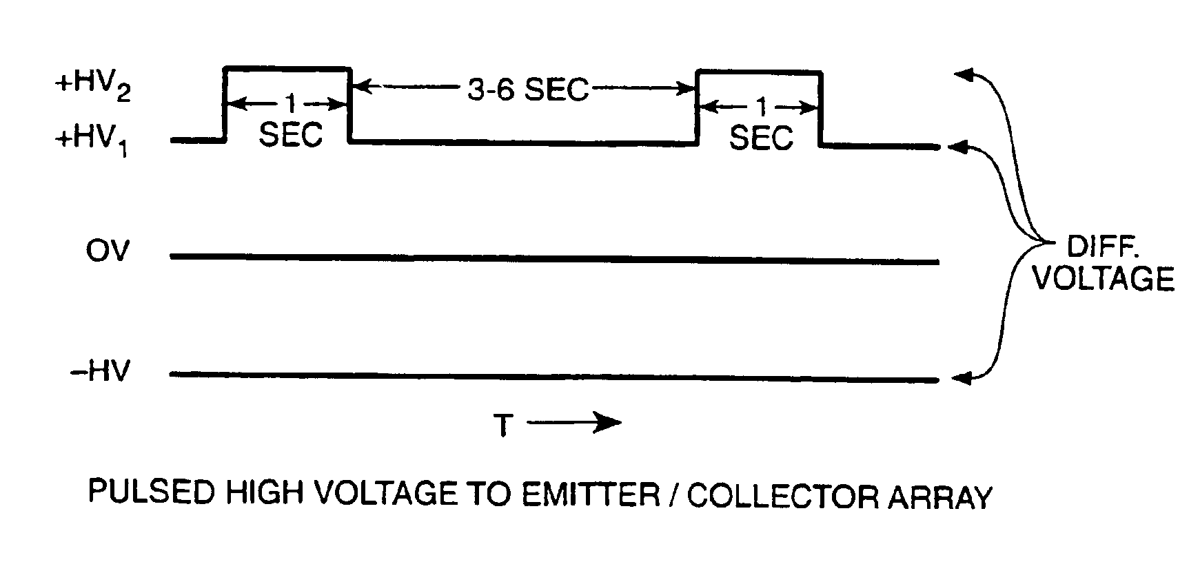
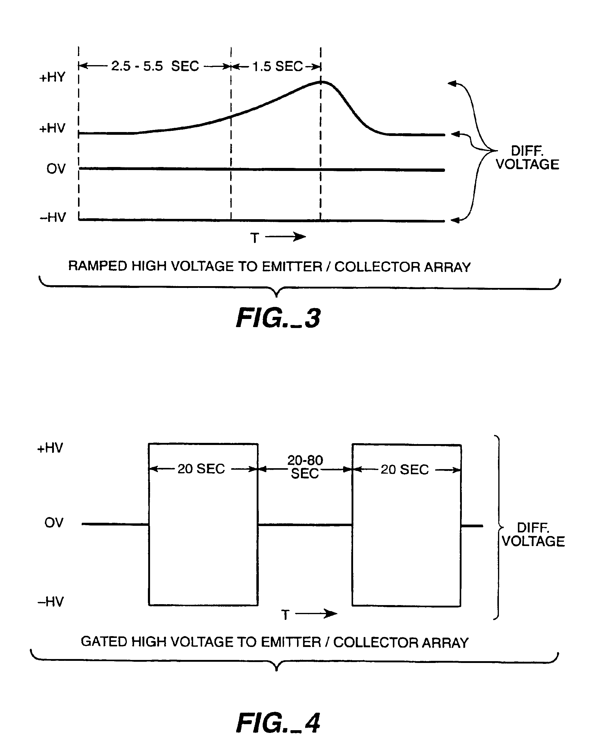
The patent describes methods for controlling the production of ozone in ion wind devices. The methods involve varying the high voltage potential across the device's emitter and collectors over time to create a "wave effect" of airflow. This results in higher acceleration and higher airflow velocities, which reduces ozone production. The methods include a switching method, a ramping method, and a gate method, which can be used alone or in combination with each other or other ozone control methods. Overall, the methods improve the performance and efficiency of ion wind devices while reducing the production of ozone.

Problems solved by technology

The U.S. Food and Drug Administration has determined that indoor airborne ozone in concentrations above 50 ppb (parts per billion) may be hazardous to humans.
NIOSH has ruled that indoor concentrations of ozone above 100 ppb may be hazardous to humans.
Devices which utilize high voltage electric fields to generate atmospheric plasma, corona discharge and air ions are all susceptible to generating the allotrope, ozone.

Method used


Image

  • Method and apparatus to reduce ozone production in ion wind device
  • Method and apparatus to reduce ozone production in ion wind device
  • Method and apparatus to reduce ozone production in ion wind device

Examples


Embodiment Construction

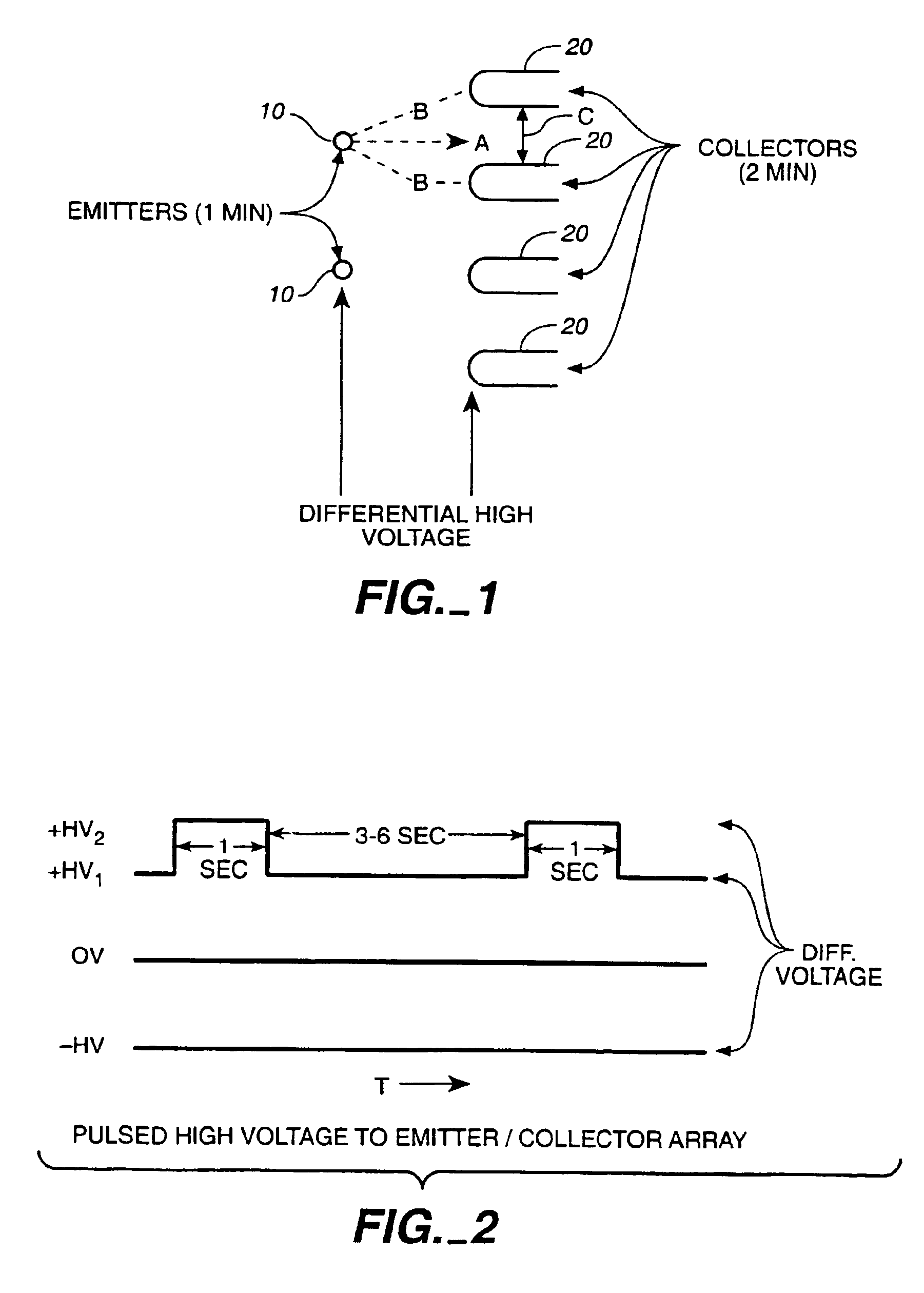
[0014]FIG. 1 refers to a typical ion wind array such as described in Lee U.S. Pat. No. 4,789,801. The emitter or emitters 10 are typically constructed of 0.1 mm pure tungsten wire and may be of any length. The collectors (sometimes referred to as accelerators) 20 are typically constructed of any non corrosive conductive material such as copper, aluminum, stainless steel, or brass. The emitter 10 is always located opposite and at the center (A) of the opening of the collectors 20. The equidistant (B) of the emitter 10 to the leading edge (radius) of the collector20 may vary depending upon desired operational effect, but is typically one inch. This is also true of the spacing (C) between the collectors 20.

[0015]The differential voltage applied across the emitter / collector array must be at least 6,500 volts in order to effect any substantial ion mobility and subsequent airflow. Typical configurations consist of applying a positive high voltage to the emitter 10 and a negative high volt...


PUM


Abstract

A method to limit ozone production in wind ion devices while simultaneously realizing incidents of high acceleration in such devices varies the high voltage potential across the array of emitter(s) (10) and collectors (20) over time in such a manner as to generate a wave effect of airflow. The variance may be achieved by switching, ramping, or gating the high voltage potential delivered to the array.

Description

[0001]This application claims the benefit of Provisional Application Ser. No. 60 / 173,075, filed Dec. 24, 1999.BACKGROUND OF THE INVENTION[0002]1. Technical Field[0003]This invention relates generally to ion generators and ion wind devices, and more specifically to an improved method and apparatus for reducing the production of ozone in ion wind devices.[0004]2. Background Art[0005]Ion wind devices such as described in Lee U.S. Pat. No. 4,789,801 (incorporated herein by reference) provide accelerated gas ions generated by the use of differential high voltage electric fields between an array of one or more emitters and a plurality of collectors (accelerators). The ions are entrained in the ambient bulk gases, causing the gases to flow. Gas velocities can reach as high as eight hundred feet per minute. However, the high voltage electric fields used to generate the gas ions and provide the force necessary for gas acceleration are also responsible for creating molecular dissociation reac...

Claims


Application Information

Patent Timeline
Patent Type & Authority Patents(United States)
IPC IPC(8): B03C3/38B03C3/34
CPCB03C3/38B03C2201/14F24F2003/1685F24F8/40
Inventor LEE, JIM L.
Owner TESSERA INC
Learn More