Electrical injury protection system using radio frequency transmission

a radio frequency transmission and electric shock technology, applied in the direction of electric signalling details, instruments, transportation and packaging, etc., can solve the problem of excessive artificial line ground current, achieve convenient and simple manner, shorten the circuit breaker tripping delay, and increase protection

Inactive Publication Date: 2005-05-24
HEALTH & HUMAN SERVICES CENTS FOR DISEASE CONTROL & PREVENTION GOVERNMENT OF THE UNITED STATES OF AMERICA THE AS REPRESENTED BY THE SEC OF THE DEPT OF
View PDF8 Cites 38 Cited by
  • Summary
  • Abstract
  • Description
  • Claims
  • Application Information

AI Technical Summary

Benefits of technology

[0009]Another object is to provide devices and methods for proximity and/or electrical contact detection between a worker and a power line using a RF transmission receiver or controller which can be connected in a convenient and simple manner to the power line. The simplicity of the devices and methods of the present invention are more likely to be used consistently and properly, thereby providing increased protection. In one embodiment of the invention, the receiver and/or controller is connected with the power line through an electrical receptacle of the power line. If desired, the receiver and/or controller can be directly wired or connected to the power line.
[0010]Another object is to provide devices and methods for proximity and/or electrical contact detection between a worker and a power line having a tripping mechanism which can de-energize the power line by outputting excessive artificial line-neutral current to trip an existing circuit breaker on the power line and which doe...

Problems solved by technology

When activated, the fast-acting tripping mechanism causes an artificial excessive line-neutral current to trip the circuit breaker of the p...

Method used


Image

  • Electrical injury protection system using radio frequency transmission
  • Electrical injury protection system using radio frequency transmission
  • Electrical injury protection system using radio frequency transmission

Examples


example

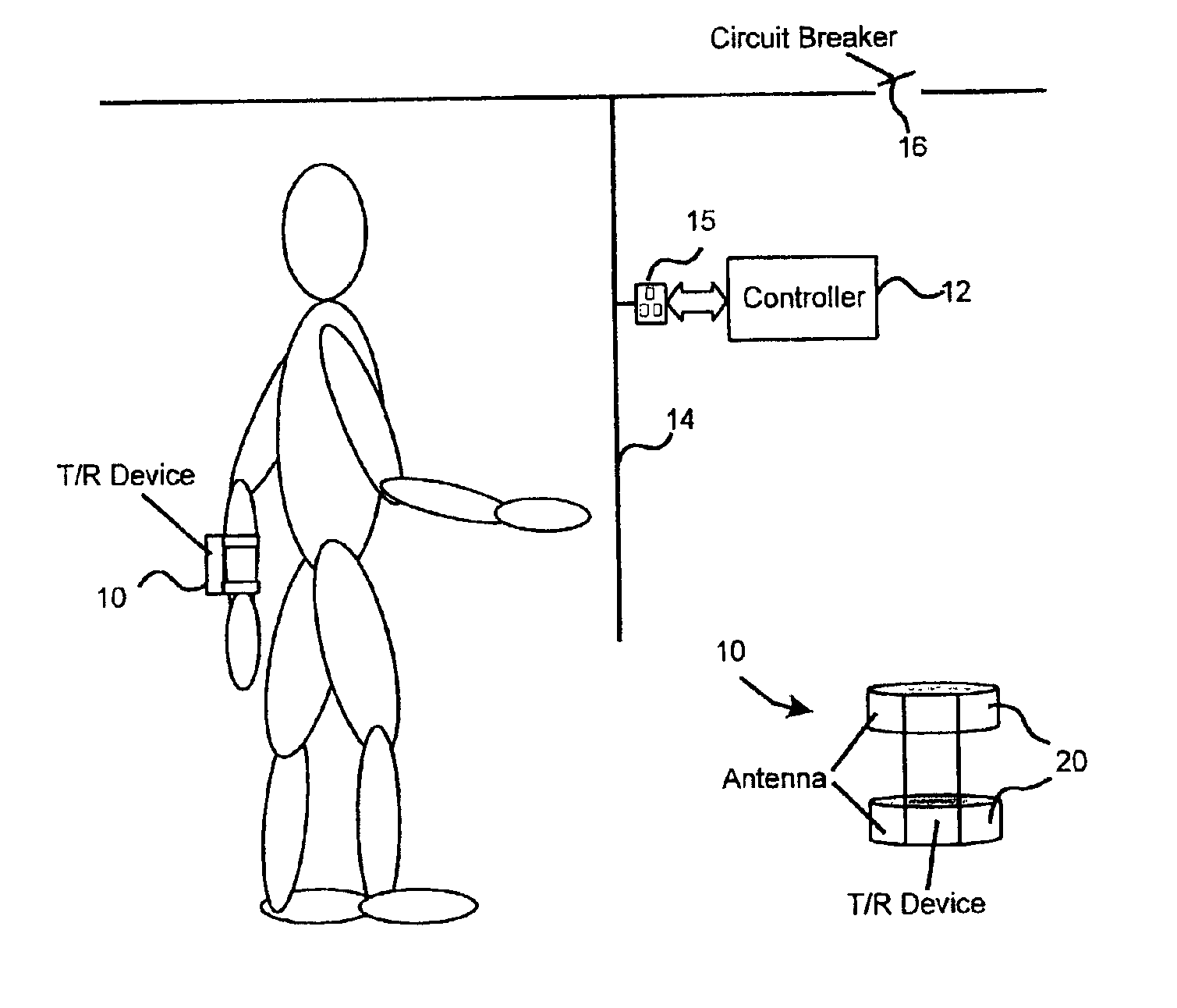
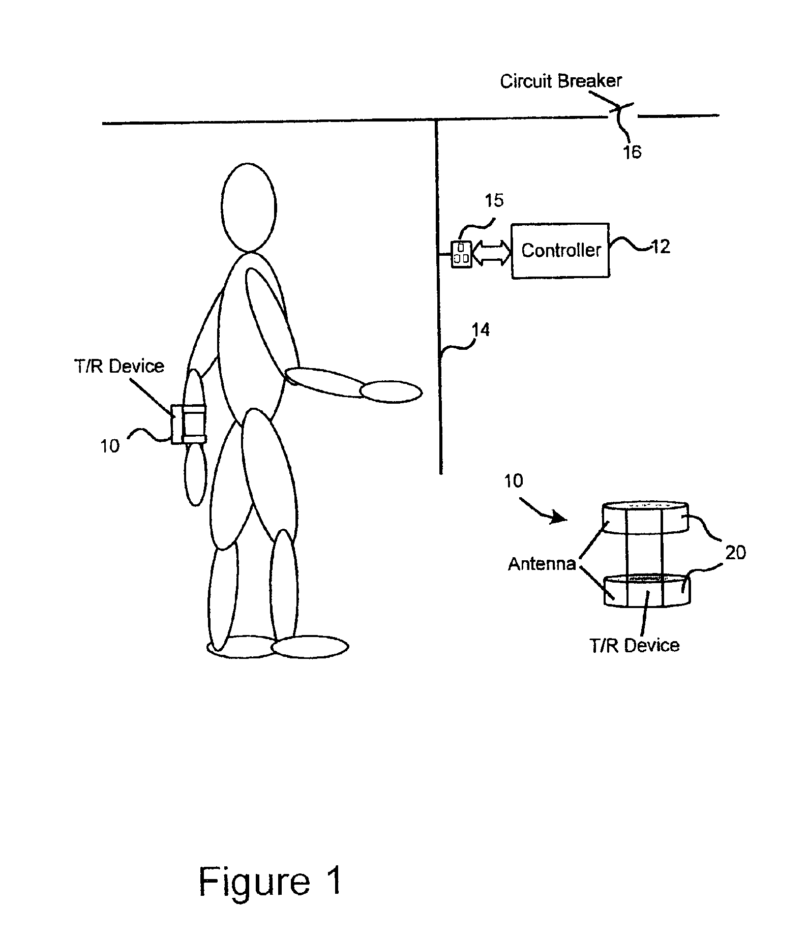
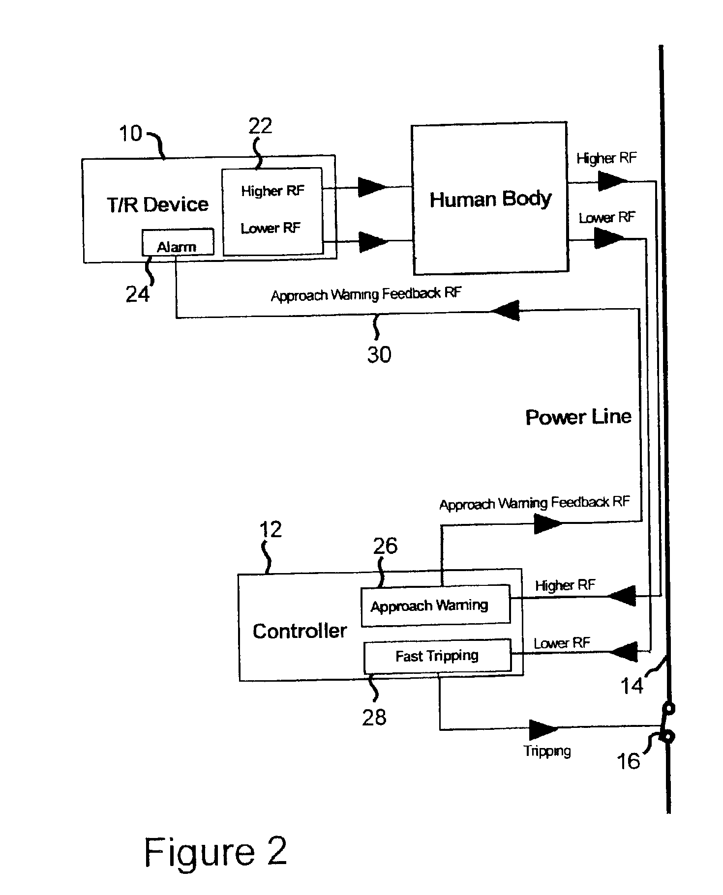
[0056]To demonstrate the feasibility of the present personal electrical injury prevention system, the RF transmission loss between a human body and a simulated power line was determined. The experimental setup consisted of a RF signal generator, a pair of conductive straps bound to a human subject's right wrist 10 cm apart, a 50-m AWG 12 simulated power line cable, and a spectrum analyzer with its input connected with the power line cable. During the experiment, an RF signal with 2 volts of amplitude and a sweeping frequency from 98.8 kHz to 40.6 MHz was transmitted from the signal generator to the pair of conductive straps bound on the subject's right wrist through a coaxial cable with grounded shielding. The RF signal was transmitted via the subject's body into the air. The subject first laid his / her right hand on the power line insulation, and the spectrum analyzer, which was connected to the power line cable, measured the transmission loss at all sweeping frequency points. Then ...


PUM


Abstract

A personal electrical injury protection system is provided which can be worn by electricians, construction workers, or other individuals working around or with low-voltage lines (i.e. generally less than about 600 volts). The personal electrical injury protection system has both a proximity warning component which provides a warning of potential electrical hazards upon close approach to the low-voltage power line and an electrical contact protection component which turns off the power upon actual electrical contact with the power line. The present personal electrical protection system relies on a radio frequency transmitter attached to the worker or person to be protected and a radio receiver/controller connected to the power line. The radio frequency transmitter has a low frequency generator which is used for electrical-contact protection and a high frequency generator which is used for proximity warning.

Description

CROSS-REFERENCE TO RELATED APPLICATIONS[0001]This is the National Stage of International Application No. PCT / US01 / 40181, filed Feb. 23, 2001, and claims the benefit of U.S. Provisional Application No. 60 / 186,860, filed Mar. 3, 2000.FIELD OF THE INVENTION[0002]The invention relates to electrical injury protection systems and, more particularly, to personal electrical protection systems which provide warnings of potential electrical hazards upon close approach to low-voltage power lines (generally less than about 600 volts) and which turn off the power upon electrical contact with the power line. The present personal electrical injury protection systems relies on a radio frequency transmitter attached to the worker or person to be protected and a radio receiver / controller connected to the power line.BACKGROUND OF THE INVENTION[0003]Electrocution is a serious cause of occupational fatality which ranked fifth among occupational fatalities in the United States from 1980 to 1995 with 6,24...

Claims


Application Information

Patent Timeline
IPC IPC(8): H02H5/00H02H5/12B66C15/06G08B21/00G08B21/02
CPCH02H5/12
Inventor ZENG, SHENGKEPOWERS, JR., JOHN R.JACKSON, LARRY L.CONOVER, DAVID L.
Owner HEALTH & HUMAN SERVICES CENTS FOR DISEASE CONTROL & PREVENTION GOVERNMENT OF THE UNITED STATES OF AMERICA THE AS REPRESENTED BY THE SEC OF THE DEPT OF
Why Eureka
Try Eureka