Image processing device and image processing method

Inactive Publication Date: 2005-05-24
SEIKO EPSON CORP
View PDF9 Cites 18 Cited by
  • Summary
  • Abstract
  • Description
  • Claims
  • Application Information

AI Technical Summary

Benefits of technology

[0008]In view of the foregoing, an object of the present invention is to provide an image process

Problems solved by technology

However, since the frequency components contained in an actual original image are infinitely large, it is not possible to restore high frequency components contained in the original image by the aforesaid interpolation methods.
However, processing time is

Method used


Image

  • Image processing device and image processing method
  • Image processing device and image processing method
  • Image processing device and image processing method

Examples


first embodiment

[0064]1. First Embodiment

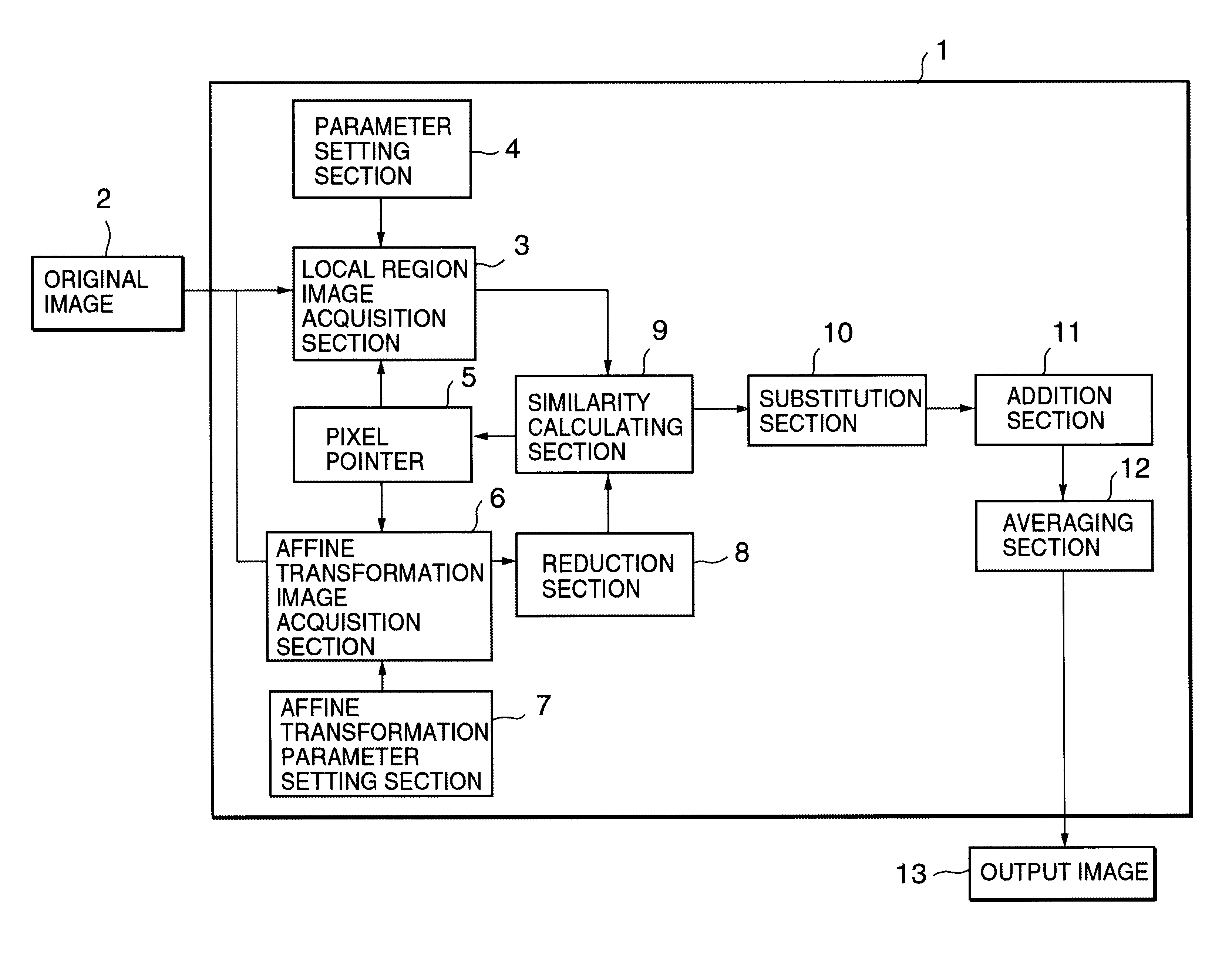
[0065]FIG. 1 to FIG. 4 are block diagrams illustrating the layout of an image processing device according to a first embodiment of the present invention.

[0066]A main image processing device 1 applies prescribed image processing to an original image that is input from original image holding section 2 and outputs this processed image to output image holding section 13. Original image holding section 2 and output image holding section 13 are constituted of memories etc. Original image holding section 2 and output image holding section 13 may be incorporated in the layout of image processing device 1, or may be respectively separately constructed from image processing device 1. For example, a PC card may provide original image holding section 2 and output image holding section 13, with the original image data being read from the PC card on which the original image is recorded and the processed image being written back to an empty region of the same PC card.

[0067...

second embodiment

[0091]2. Second Embodiment

[0092]Next, a second embodiment of the present invention is described with reference to FIG. 5. In the following embodiments, structural elements which are the same as structural elements described above are given the same reference symbols and further description thereof is omitted. A characteristic feature of this embodiment is that an affine transformation image of the same size as the local region image is directly acquired by acquiring partial scattered pixels from the image region corresponding to the affine transformation image.

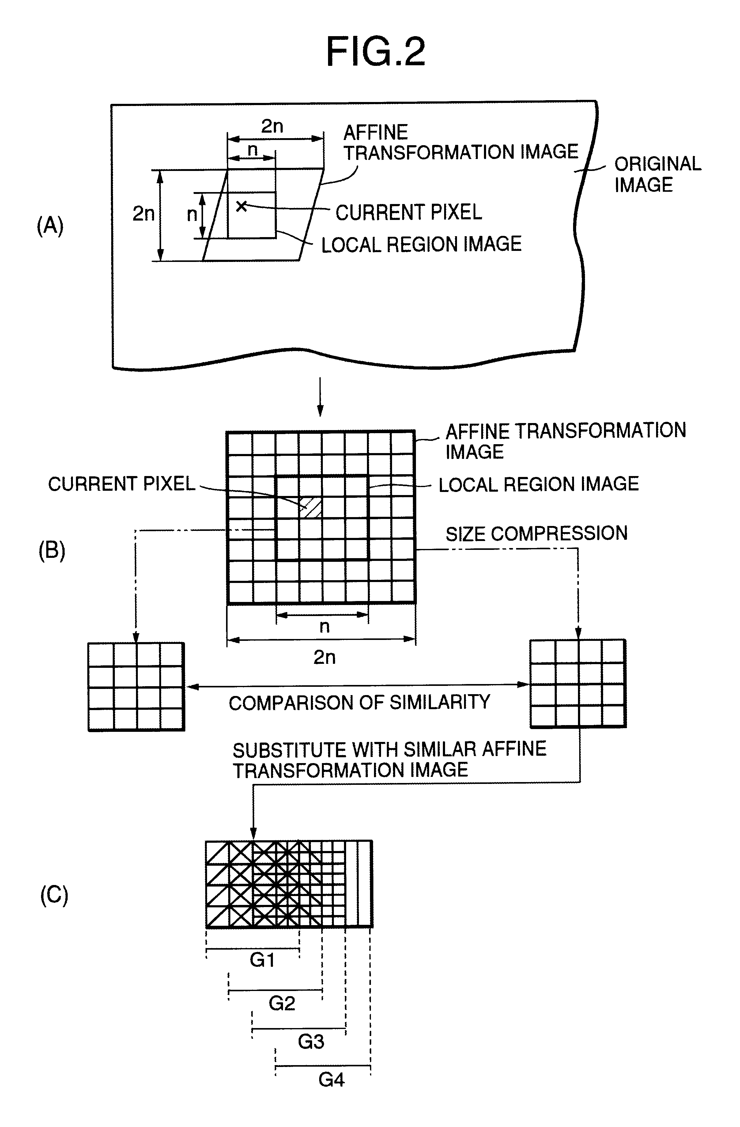
[0093]As shown in FIG. 5(a), an affine transformation image of the same size as the local region image can be obtained by acquiring an affine transformation image with size 2n×2n and reducing the size of this affine transformation image that is thus obtained.

[0094]In contrast, as shown in FIG. 5(b), from a region corresponding to an affine transformation image of size 2n×2n, instead of acquiring all the pixels in this region, ...

third embodiment

[0095]3. Third Embodiment

[0096]Next, a third embodiment of the present invention is described with reference to FIG. 6. A characteristic feature of this embodiment is that, based on properties of the original image etc, it is made possible to set the values of the affine transformation parameters for each color component.

[0097]First of all, when performing image improvement using the image processing device, the user can select exclusively (S21) either color bleeding prevention mode or sharp mode. In color bleeding prevention mode, the fractal interpolation according to the present invention is applied to the R component and B component of the original image represented by an RGB colorimetric system, in order to suppress color bleeding. In contrast, in sharp mode, the fractal interpolation is applied solely to the G component in order to make the outline etc of the image clear. For example, in a digital camera or the like in which a single unit is formed by in each case one R compon...


PUM


Abstract

The object of the invention is to convert a low-quality original image into a high-quality fractal-interpolated image. From a low-quality original image, original image blocks of n×n size, which are mutually overlapping and each centered on each pixel of the original image, are acquired. Also, similar image blocks of 22n size, which are each similar to each of the original image blocks, are detected from the original image by affine transformation. The detected similar image blocks are reduced to the same size as the original image blocks, and then substituted for the original image blocks respectively. Then, overlapping portions of the substituted similar image blocks are adjusted by averaging. As a result, a high-quality fractal-interpolated image is generated.

Description

BACKGROUND OF THE INVENTION[0001]1. Field of the Invention[0002]The present invention relates to an image processing device and image processing method capable of converting for example a low-quality image into a high-quality image by interpolation.[0003]2. Description of the Related Art[0004]For example when converting a low-quality digital image to a high-quality digital image, converting a low resolution image to high resolution, or enlarging an image, image interpolation is performed by for example inserting new pixels between one original pixel and another. Known methods of digital image interpolation include for example the nearest-neighbor interpolation method (also called the zero-order holding method), linear interpolation method (also called the straight-line interpolation method, collinear interpolation method, or bilinear method), cubic convolution interpolation method (also called the bi-cubic method).[0005]Since the basic concept of the methods of interpolation describ...

Claims


Application Information

Patent Timeline
IPC IPC(8): G06T9/00
CPCG06T9/001
Inventor MATSUHIRA, MASATOSHI
Owner SEIKO EPSON CORP
Why Eureka
Try Eureka