
Method for adjusting system clocks using dynamic clock ratio detector to detect clock ratio between clock domain of driver and counting receiver clock domain

Inactive Publication Date: 2005-05-24
IBM CORP
View PDF12 Cites 5 Cited by
  • Summary
  • Abstract
  • Description
  • Claims
  • Application Information

AI Technical Summary

Benefits of technology

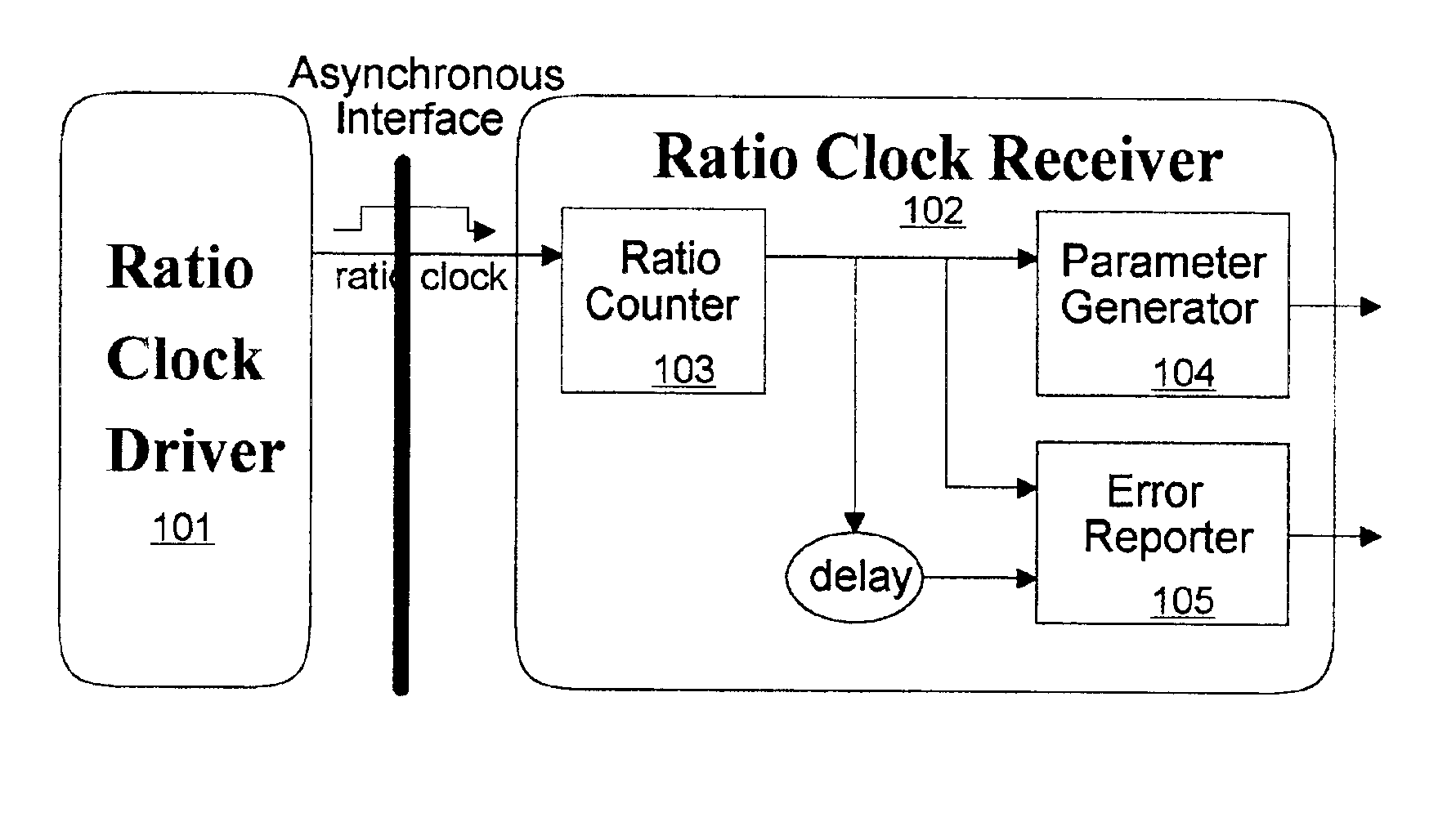
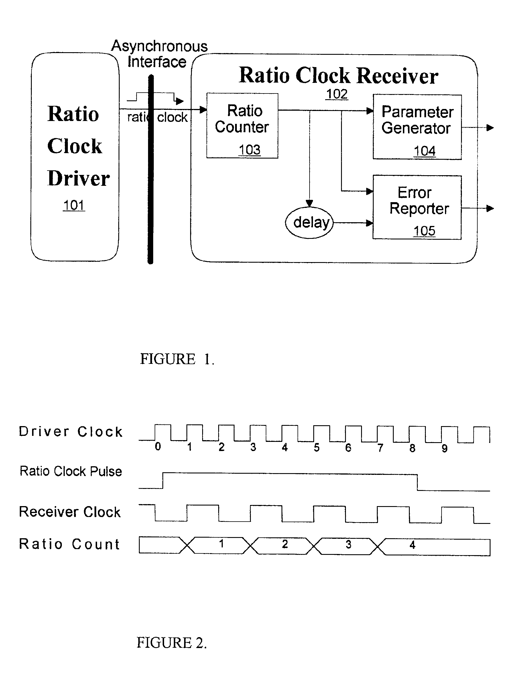
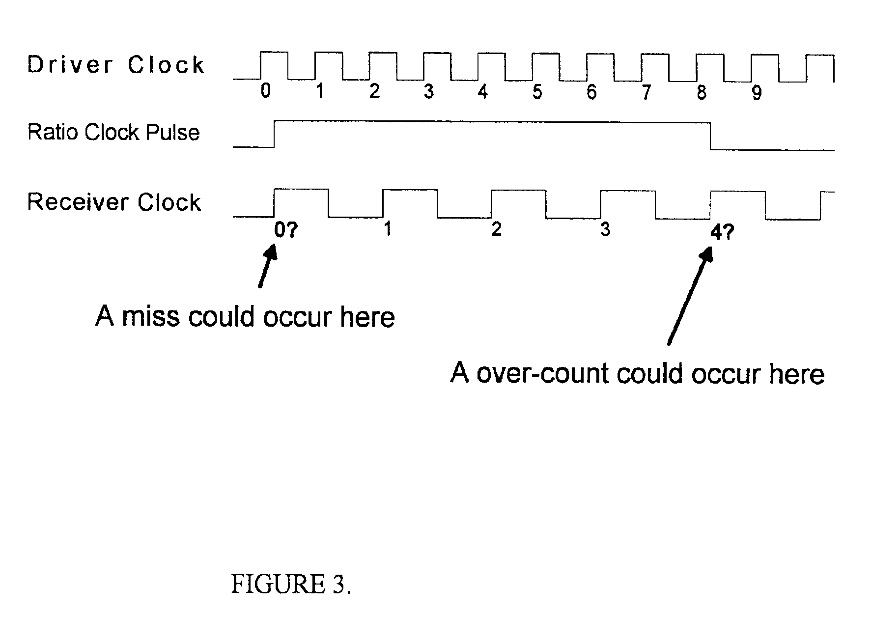
[0004]We have found it desirable to develop the capability of using a dynamic clock ration detector to allow use of Asynchronous Interfaces in CP and MSC organization which allows a manufacturer to breaks the dependency among clocks in CP, SC and MSC, and allows them to be optimized to desired clock frequency independently. In accordance with our invention we have provided a dynamic clock ratio detector that constantly monitors system clocks and detects the clock ratio between multiple clock domains on-the-fly. In accordance with our preferred embodiment of our invention, our dynamic clock ratio detector for a computer circuit system is used to determine the ratio between two clock domains of the computer circuit system. The detector has a driver and a receiver, which reside in different clock domains. The driver constantly produces a ratio clock pulse to the receiver. The ratio-counter in the receiver counts the pulse width based on its local clock cycles. The clock ratio detector has many features, including absorbing the meta-stability effect when the pulse crosses an asynchronous interface. Our clock ratio detector prevents output counts oscillation, provides an adjustable ratio-detecting coverage range, a programmable system-parameter generator, and a programmable error reporter.

Problems solved by technology

This design strategy simplifies the design implementation and debug procedure, but has certain limitations resulting which can make it impossible to optimize efficiency of particular elements of the computer system in order to maximize the system performance.

Method used


Image

  • Method for adjusting system clocks using dynamic clock ratio detector to detect clock ratio between clock domain of driver and counting receiver clock domain
  • Method for adjusting system clocks using dynamic clock ratio detector to detect clock ratio between clock domain of driver and counting receiver clock domain
  • Method for adjusting system clocks using dynamic clock ratio detector to detect clock ratio between clock domain of driver and counting receiver clock domain

Examples


Embodiment Construction

[0010]As we found it desirable to develop the capability of using a Asynchronous Interfaces in CP and MSC organization which allows a manufacturer to breaks the dependency among clocks in CP, SC and MSC, and allows them to be optimized to desired clock frequency independently we recognized that this dramatic advantage would not normally come without cost. Besides adding design and verification efforts of the asynchronous interface, the designers have to maintain multiple sets of parameters used in system (system settings) for different clock ratios instead of just one set as before. Moreover, whenever the clock ratios among system clocks change, the system has to go through power-on reinitialization process again, which is a time-consuming procedure.

[0011]In accordance with our invention we have provided a dynamic clock ratio detector for one or more computer circuits which can be manufactured as ASICs that constantly monitors system clocks and detects clock ratio on-the-fly. This c...


PUM


Abstract

Disclosed is a method and a computer circuit design for a dynamic clock ratio detector. The detector is used to determine the ratio between two clock domains. The detector has a driver 101 and a receiver, which reside in different clock domains. The driver 101 constantly produces a ratio clock pulse to the receiver. The ratio-counter in the receiver counts the pulse width based on its local clock cycles. The clock ratio detector has many features, including absorbing the meta-stability effect when the pulse crosses an asynchronous interface. The clock ratio detector prevents output counts oscillation, provides an adjustable ratio-detecting coverage range, a programmable system-parameter generator 104, and a programmable error reporter 105.

Description

FIELD OF THE INVENTION[0001]This invention is related to application specific integrated circuit (ASIC) design and in particular to the ASICs having multiple clock domains and to a method for setting of those ASICs needs to dynamically adjust their clock domains with different clock ratios among clock domains.[0002]Trademarks: S / 390 and IBM are registered trademarks of International Business Machines Corporation, Armonk, N.Y., U.S.A. Other names may be registered trademarks or product names of International Business Machines Corporation or other companies.BACKGROUND[0003]Routinely now it is possible to generate an internal clock signal in a memory chip that is synchronized to an external clock signal, as in U.S. Pat. No. 6,340,904, entitled “Method and apparatus for generating an internal clock signal that is synchronized to an external clock signal” of Troy A Manning of Micron Technology, Inc., Boise, Id. Another of Troy Mannings patents, U.S. Pat. No. 6,338,127,entitled “Method an...

Claims


Application Information

Patent Timeline
IPC IPC(8): G06F1/04
CPCG06F1/04
Inventor KARK, KEVIN W.WANG, LIYONG
Owner IBM CORP
Learn More