Floor strip

a technology of floor strips and strips, applied in the field of floor strips, can solve the problems of conventional floor strips not adequately providing a transition between different floor types, previously known strips not going well together with all the other floor patterns, and floor strips generally not adequately matching the pattern of the other portions of the floor

Inactive Publication Date: 2005-05-31
PERGO
View PDF60 Cites 123 Cited by
  • Summary
  • Abstract
  • Description
  • Claims
  • Application Information

AI Technical Summary

Benefits of technology

[0016]Often at least one of the paper sheets of the postforming laminate impregnated with thermosetting resin, preferably the uppermost one, is coated with hard particles, e.g., those having a Moh's hardness of at least 6, preferably between 6 and 10, similar to the Moh's hardness of at least silica, aluminium oxide, diamond and / or silicon carbide. The hard particles have an average particle size of about 1-80 μm, preferably about 5-60 μm evenly distributed over the surface of the paper sheet. In a preferred embodiment the hard particles are applied on the resin impregnated paper surface before the resin has been dried. The hard particles improve the abrasion resistance of the laminate. Hard particles are used in the same way at the production of laminates which are subject to a hard wear such as flooring laminates.
[0017]The abrasion resistance of the post-forming laminates is tested according to the European standard EN 438-2 / 6: 1991. According to this standard the abrasion of the decor sheet of the finished laminate to the so-called IP-point (initial point) is measured, where the starting abrasion takes place. The IP-value suitably lies within the interval 3000-20000, preferably 3000-10000 revolutions. Thus, the manufacturing process according to the invention makes it possible to produce laminate clad profiles with the same surface pattern and about the same abrasion resistance as the laminate floorings they are intended to be used together with.
[0019]In order to overcome the problems associated with transitioning between carpet and tile, differing textures of tiles or differing heights of tiles, the second plane may have a tab portion on its tile / carpet engaging surface depending orthogonally away from the second plane and displaced away from the first plane. The tab is used to engage a reducer that extends between the floor surface and the engagement surface of the second plane. The reducer is configured to maintain a horizontal orientation of the second plane and provide a smoother transition between the tile surfaces in the finishing, transition or dilatation profile when they are used between uneven tile surfaces, differing tile textures or between carpet and tile. The tab portion fits into a groove on the upper surface of the reducer in mating fashion to create a solid lock between them.
[0020]Alternatively, the tab portion may be engaged into the edge of a tile panel on the floor. In this situation, the tiles adjacent to the transition area may require a groove cut into them near the transition. Such allows the tab portion to maintain a firm and locked relationship with the tile surface and provide a better transition between the tile surface and the respective profile. Further, a tab portion may be provided on both sides of the second plane respective to the first plane to further smooth the transition area between the first tile surface, the floor strip and the second surface.
[0022]This inventive floor strip according to the above may be used as a transition piece between various tongue and groove panels to provide a smooth and aesthetic transition between floor sections having dissimilar surfaces, such as those between a carpeted area and a tiled area, a thin tile area and a hardwood floor, two tile areas having differing textures, etc.

Problems solved by technology

However, such floor strips generally do not adequately match the pattern of the other portions of the floor.
Previously known strips do not go well together with all the other floor patterns.
However, conventional floor strips do not adequately provide a transition between differing floor types because they cannot adequately cover the gap between the differing floor coverings or the differing heights of the tiles.
However, it also a problem for sellers of floor strips to inventory differing types of transition profiles, especially in a pattern or color to match a single floor.

Method used


Image

  • Floor strip
  • Floor strip
  • Floor strip

Examples


Embodiment Construction

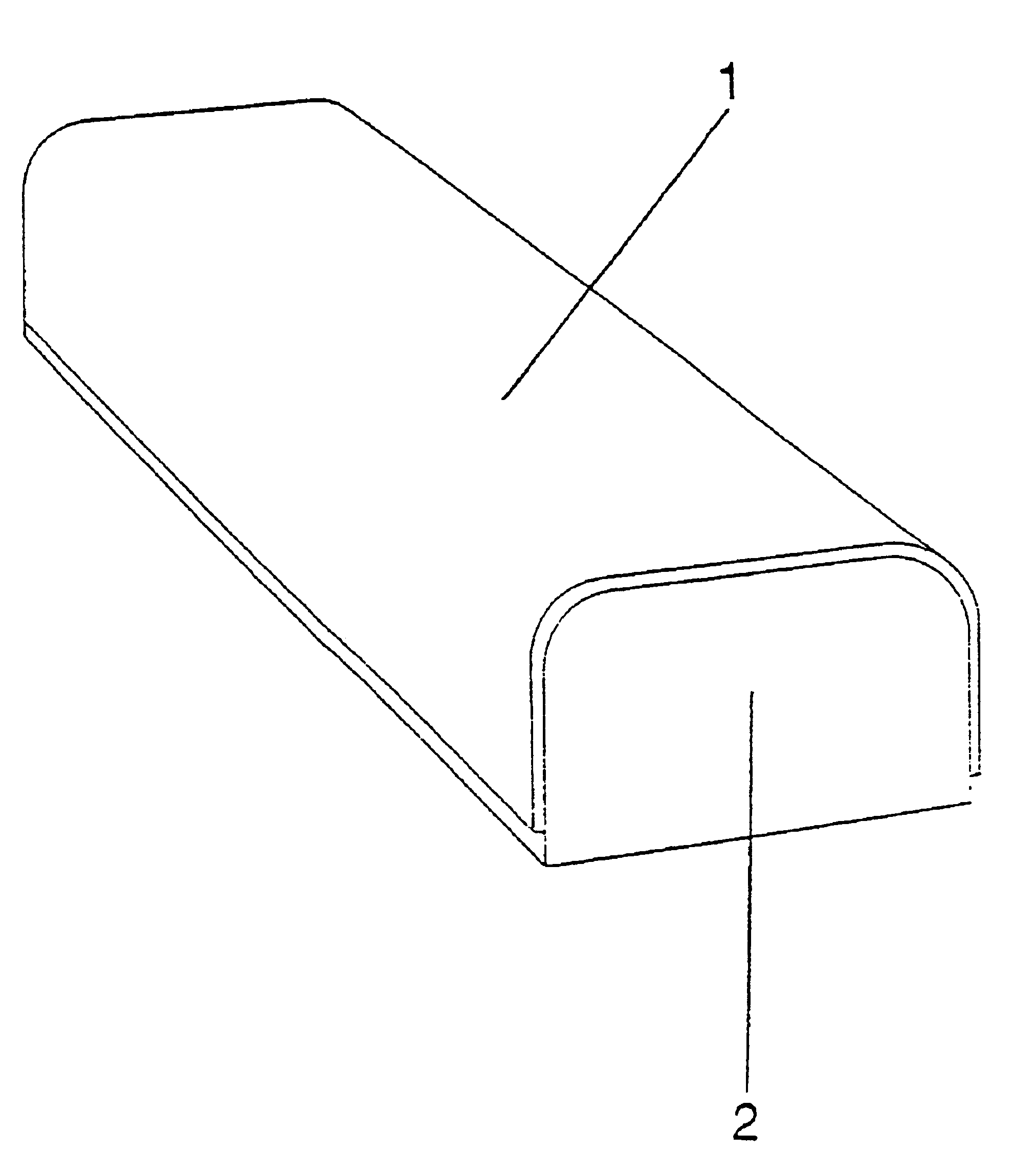
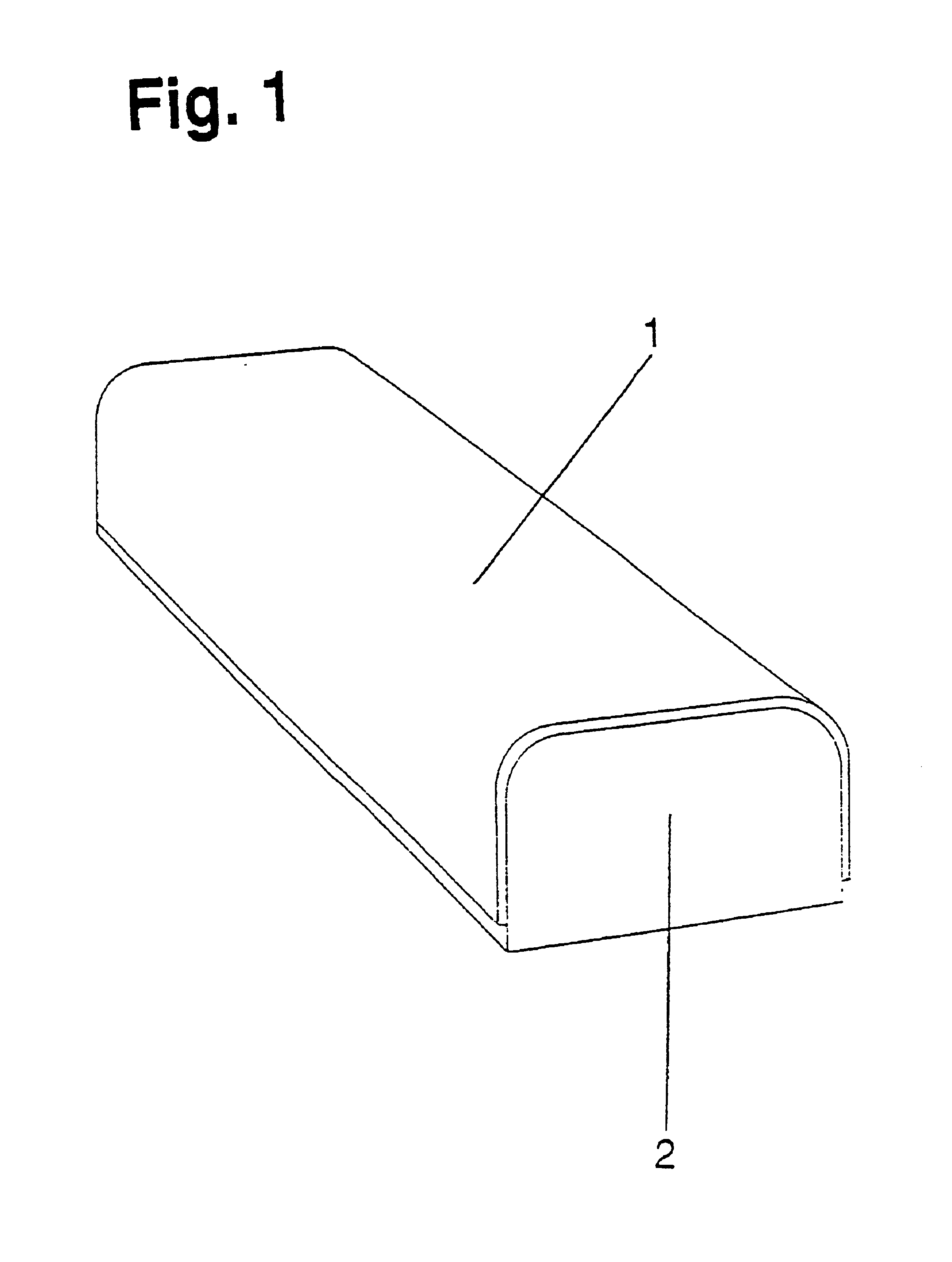
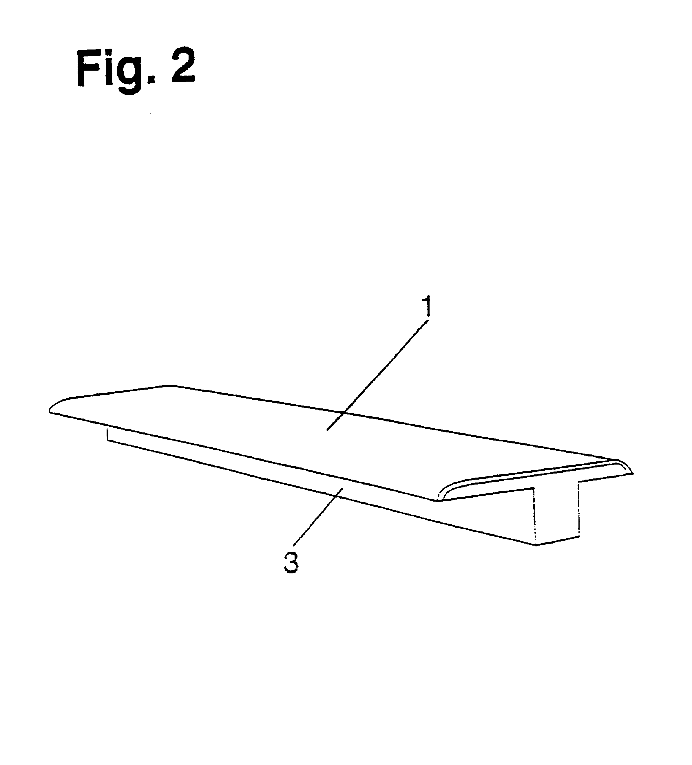
[0034]In the figures of illustrating a floor strip 100, the thickness of the post-forming laminate 1 has been magnified as compared to the size of the carrier 2 and the profiles, e.g. 3-5 respectively, to better illustrate that a post-forming laminate 1 is glued to the carrier 2 and the profiles 3-5 respectively. Of course the FIGS. 1-4 only show one embodiment of the carrier 2 and the profiles 3-5 respectively which can be produced according to the invention. Various other designs are possible as shown in the other drawing figures.

[0035]For example in one embodiment, a roll of transparent so-called overlay paper of α-cellulose with a surface weight of 25 g / m2 is impregnated with an aqueous solution of melamine-formaldehyde resin to a resin content of 70 percent by weight calculated on dry impregnated paper. Immediately after the impregnation, aluminium oxide particles with an average particle size of 50 μm are applied to the upper side of the paper in an amount of 7 g / m2 by means o...


PUM

PropertyMeasurementUnit
particle sizeaaaaaaaaaa

Abstract

A thin decorative thermosetting laminate of postforming quality is glued to a longitudinal carrier to form a floor strip. The laminate has a thermosetting resin as well as hard particles impregnated therein to increase the abrasion resistance of the laminate. The carrier generally has a cross section of a dilatation, transition or a finishing profile, depending on the intended use of the floor strip. The floor strip has a tab portion on a surface that engages a channel on a floor tile or a reducer. The tab portion locks the floor strip into place and prevents movement of the floor tile or the reducer with respect to the floor strip.

Description

CROSS REFERENCE TO RELATED APPLICATIONS[0001]This application is a continuation-in-part of U.S. Ser. No. 08 / 817,391, filed Apr. 25, 1997 now U.S. Pat. No. 6,517,935 and a continuation-in-part of U.S. Ser. No. 09 / 986,414, filed Nov. 8, 2001 now abandoned, the entire disclosures of which are hereby incorporated by reference.BACKGROUND OF INVENTION[0002]1. Field of the Invention[0003]The present invention relates to a process for the production of a floor strip such as a dilatation profile, a transition profile or a finishing profile. The present invention also relates to the features of the floor strip.[0004]2. Description of the Related Art[0005]It is previously known to produce floor strips such as metal strips, wood veneer coated strips and strips of homogeneous wood. However, such floor strips generally do not adequately match the pattern of the other portions of the floor. Thus, there is a strong desire to bring about a floor strip with the same pattern as on a floor of thermoset...

Claims


Application Information

Patent Timeline
Patent Type & Authority Patents(United States)
IPC IPC(8): E04F19/02E04F19/06E04F15/02B27N7/00B32B27/04D21H13/40D21H27/06D21H27/28E04B1/62
CPCB27N7/005B32B27/04D21H27/28E04F19/02E04F19/062E04F19/065E04F15/02005D21H13/40D21H27/06Y10T428/24174Y10T428/24182B32B37/12B32B2260/046B32B3/30B32B2419/04B32B2037/1215B32B2317/18
Inventor KORNFALT, SVENBENGTSSON, PERSJOLIN, HANSSTANCHFIELD, OLIVER
Owner PERGO
Why Eureka
Try Eureka