
Lighted supervisory system for a fuel dispensing nozzle

a supervisory system and fuel dispensing technology, applied in the direction of liquid transfer devices, packaging goods types, liquid handling, etc., to achieve the effect of simple and low-cost supervision

Active Publication Date: 2005-05-31
OPW FUEL MANAGEMENT SYST
View PDF20 Cites 94 Cited by
  • Summary
  • Abstract
  • Description
  • Claims
  • Application Information

AI Technical Summary

Benefits of technology

[0008]One advantage of the present invention is its provision of a simple and low-cost supervisory and authorization system for a fleet fuel dispensing system, whereby lighted indicia conveniently provides authorization and / or fueling status information to an operator. Additional aspects, advantages and novel features of the invention will be set forth in part in the description that follows, and in part will become apparent to those skilled in the art upon examination of the following or may be learned with the practice of the invention. The aspects and advantages of the invention may be realized and attained by means of the instrumentalities and combinations particularly pointed out in the appended claims.

Problems solved by technology

Because many designated fleet fueling sites are intended only to provide fuel to the vehicles of one or more particular fleets, these sites need not provide the amenities typically provided by a consumer gasoline station, as the fleet fueling sites are not competing for customers of the typical consumer gasoline stations.
For this reason, fleet fueling systems often involve as little expense as necessary, and accordingly are often not provided with elaborate electronic displays, for example, and typically do not have any human attendant on staff to oversee the fueling operations.
However, because budget-oriented fleet fueling systems do not involve such amenities, feedback regarding the authorization or progression of the fueling process is typically not available to an operator, and there are occasions where an operator is left to wonder why there is a delay in his vehicle receiving fuel and / or why the fleet fueling system will not dispense fuel.

Method used


Image

  • Lighted supervisory system for a fuel dispensing nozzle
  • Lighted supervisory system for a fuel dispensing nozzle
  • Lighted supervisory system for a fuel dispensing nozzle

Examples


Embodiment Construction

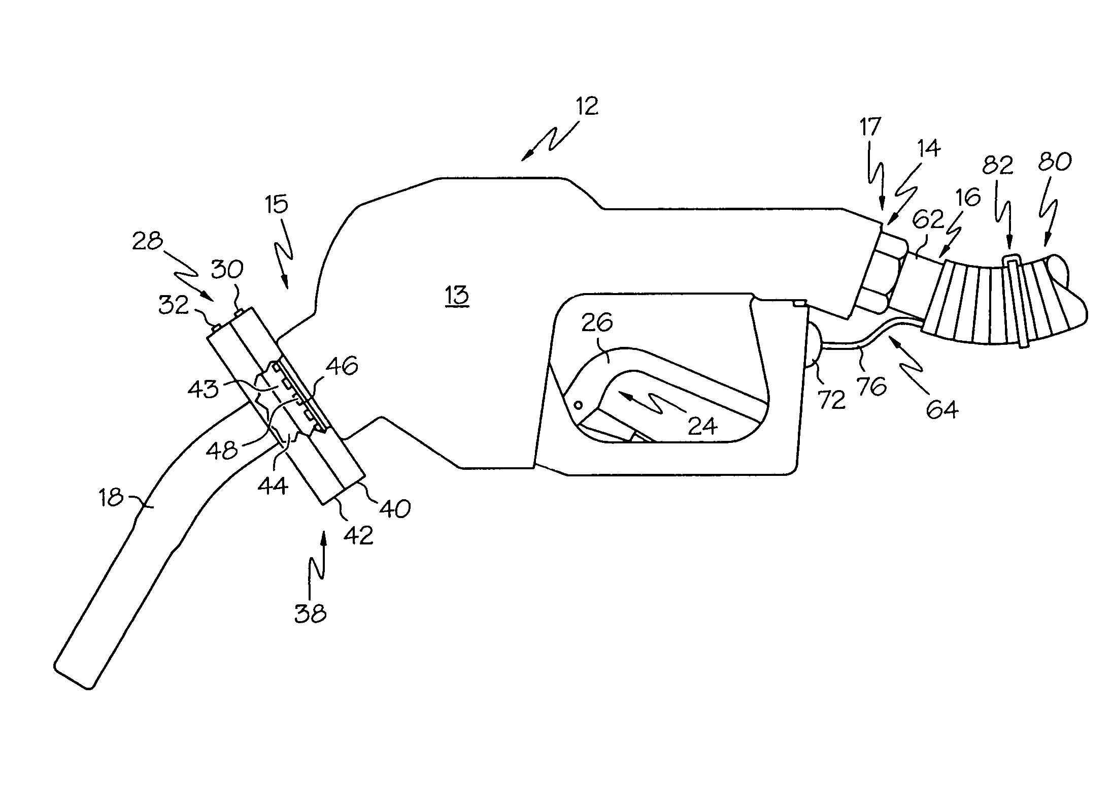
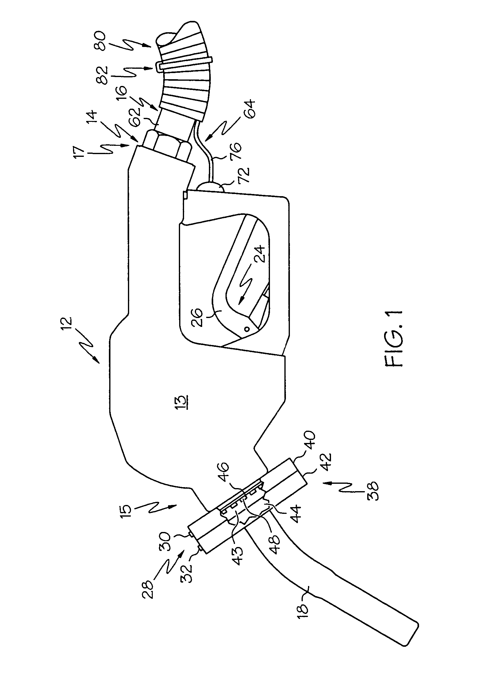
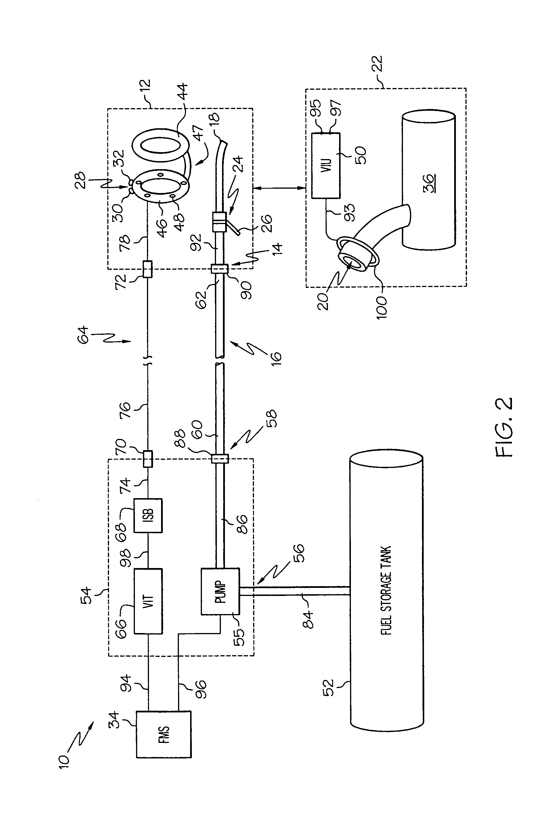
[0012]The present invention and its operation are hereinafter described in detail in connection with the views and examples of FIGS. 1–2, wherein like numbers indicate the same or corresponding elements throughout the views. Referring to FIG. 1, an exemplary nozzle 12 in accordance with the teachings of the system of the present invention is shown to include a body 13. A spout 18 is shown as being attached to body 13 near the front 15 of body 13. The spout 18 can be shaped and sized such that it can be appropriately received in a corresponding fuel entry receptacle of one or more types of vehicles. Such vehicles might include, for example, cars, vans, trucks, watercraft, and / or aircraft.

[0013]Nozzle 12 also includes fuel input port 14 disposed near the rear 17 of body 13. Fuel input port 14 can in some embodiments comprise a threaded aperture or another suitable interface for receiving a second end 62 of fuel supply hose 16. Fuel supply hose 16 is shown to be at least partially surr...


PUM


Abstract

A nozzle is provided for a fleet fuel dispensing system. The nozzle includes an input port that is adapted to receive fuel through a fuel supply hose, and a spout that is configured to dispense fuel into a fuel entry receptacle of a vehicle. A valve assembly is configured to couple the input port with the spout, and is further configured to selectively facilitate the passage of fuel from the input port to the spout. A status light is associated with the nozzle and includes a single LED that is connected with a fleet management system. The status light is configured to selectively illuminate as directed by a fleet management system. The illumination provides information as to whether a vehicle is authorized to receive fuel from the spout. A fuel dispensing system having such a nozzle is also provided.

Description

TECHNICAL FIELD[0001]The present invention relates to a visual supervisory system for association with a nozzle of a fuel dispensing system. The system includes a status light provided by at least one LED to visually communicate information as to whether a fleet vehicle is authorized to receive fuel from the nozzle, as well as other information as desired.BACKGROUND OF THE INVENTION[0002]Many commercial enterprises, municipalities, and other entities own and / or operate fleets of vehicles (e.g., cars, vans, trucks, watercraft, aircraft, etc.). Conventional fleet fueling systems have been developed in order that such vehicles can receive fuel from a designated fueling site without the need for the operator of the vehicle to pay for the fuel in a conventional manner at that time. These fleet fueling systems can track the amount of fuel dispensed to a particular vehicle over time such that fleet managers can consolidate payments to the fuel vendor without any need for operators to keep ...

Claims


Application Information

Patent Timeline
IPC IPC(8): B67D5/33B67D5/32B67D5/37B67D7/34B67D7/42
CPCB67D7/348B67D7/426B67D7/425
Inventor LATKA, WALTER G.KLIMA, RICHARD J.JARVIE, IAN FRANCIS
Owner OPW FUEL MANAGEMENT SYST
Learn More