Method and device for altering the separation characteristics of flow over an aerodynamic surface via hybrid intermittent blowing and suction

a technology of aerodynamic surface and separation characteristics, which is applied in the direction of air-flow influencers, fuselages, drag reduction, etc., can solve the problems of affecting the flow region of recirculation, causing drag penalty, etc., and achieves reduced or delaying flow separation (laminar or turbulent), less power, and greater lift-to-drag ratio

Active Publication Date: 2005-05-31
THE BOEING CO
View PDF10 Cites 40 Cited by
  • Summary
  • Abstract
  • Description
  • Claims
  • Application Information

AI Technical Summary

Benefits of technology

[0003]The present invention pertains to an AFC technique of applying intermittent suction or intake of fluid, in combination with intermittent blowing or expulsion of fluid, through the exterior surface of an airfoil in a manner reducing or delaying flow (laminar or turbulent) separation over the airfoil. This technique requires less power than is required with constant suction or constant blowing AFC techniques and provides for a greater increase in lift-to-drag ratios as compared to oscillating suction / expulsion or intermittent suction only AFC methods.
[0004]In a first aspect of the invention, a device comprises an airfoil, a fluid (gas or liquid) inlet opening, a fluid outlet opening, a pump, and first and second valves. The airfoil has an exterior surface and the fluid inlet and outlet openings each extend through the exterior surface of the airfoil. The pump is operatively connected to the fluid inlet opening and to the fluid outlet opening, and is configured and adapted to draw fluid into the airfoil through the fluid inlet opening and to expel fluid from the airfoil through the fluid outlet opening. The first valve is operatively connected between the fluid inlet opening and the pump and the second valve is operatively connected between the pump and the fluid outlet opening. The first valve is configured and adapted to allow fluid to be drawn into the airfoil through the fluid inlet opening via the pump and to prevent fluid from being expelled from the airfoil through the fluid inlet opening. The second valve is configured and adapted to allow fluid to be expelled from the airfoil through the fluid outlet opening via the pump and to prevent fluid from being drawn into the airfoil through the fluid outlet opening.

Problems solved by technology

As is the case with virtually all types of aerodynamic control surfaces, a drag penalty is usually incurred when fluid flow over the top surface (or the lower pressure surface) of the airfoil separates upstream of the trailing edge of the airfoil.
Additionally, such separation is accompanied by a detrimental recirculation flow region downstream of the separation point.

Method used


Image

  • Method and device for altering the separation characteristics of flow over an aerodynamic surface via hybrid intermittent blowing and suction
  • Method and device for altering the separation characteristics of flow over an aerodynamic surface via hybrid intermittent blowing and suction
  • Method and device for altering the separation characteristics of flow over an aerodynamic surface via hybrid intermittent blowing and suction

Examples


Embodiment Construction

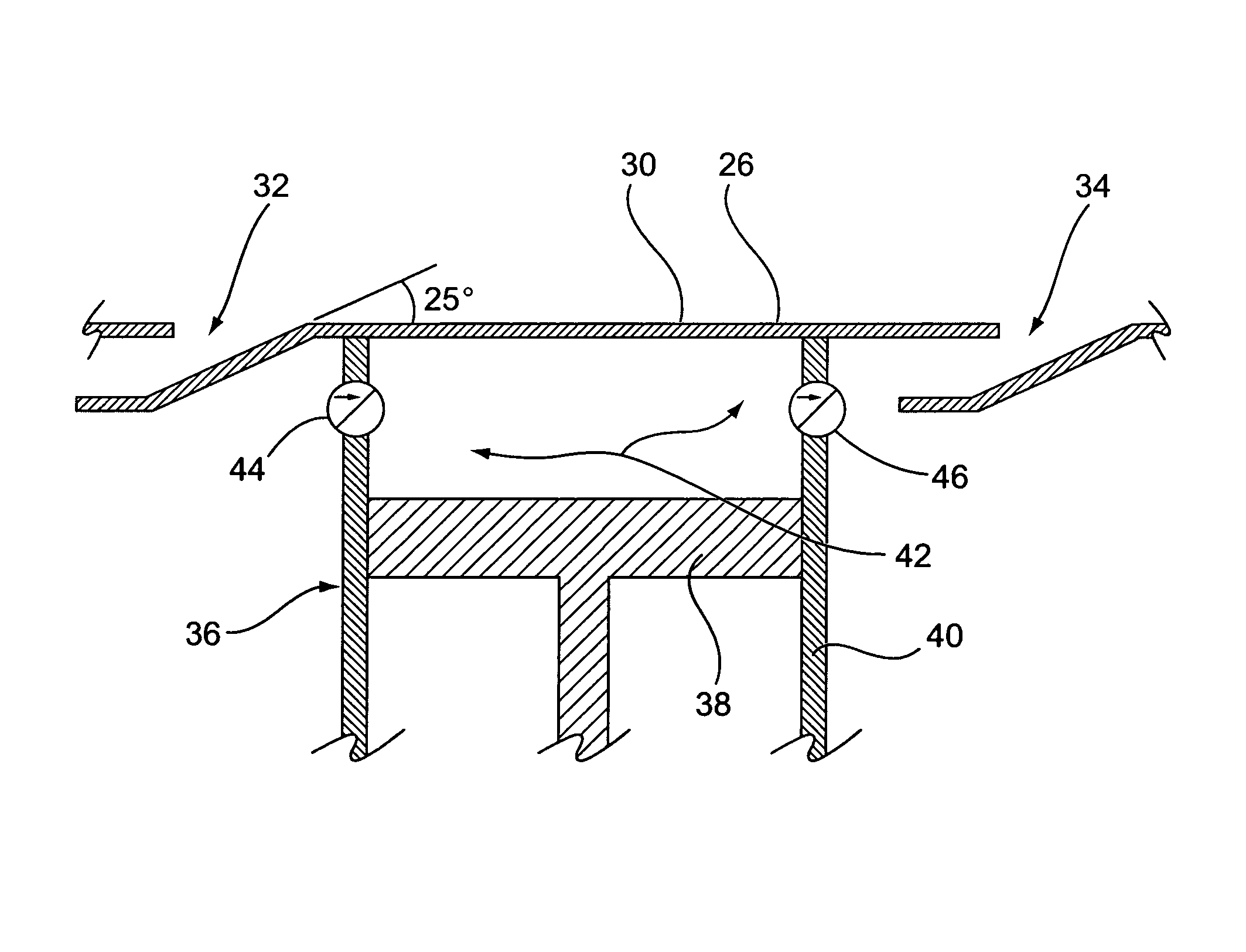
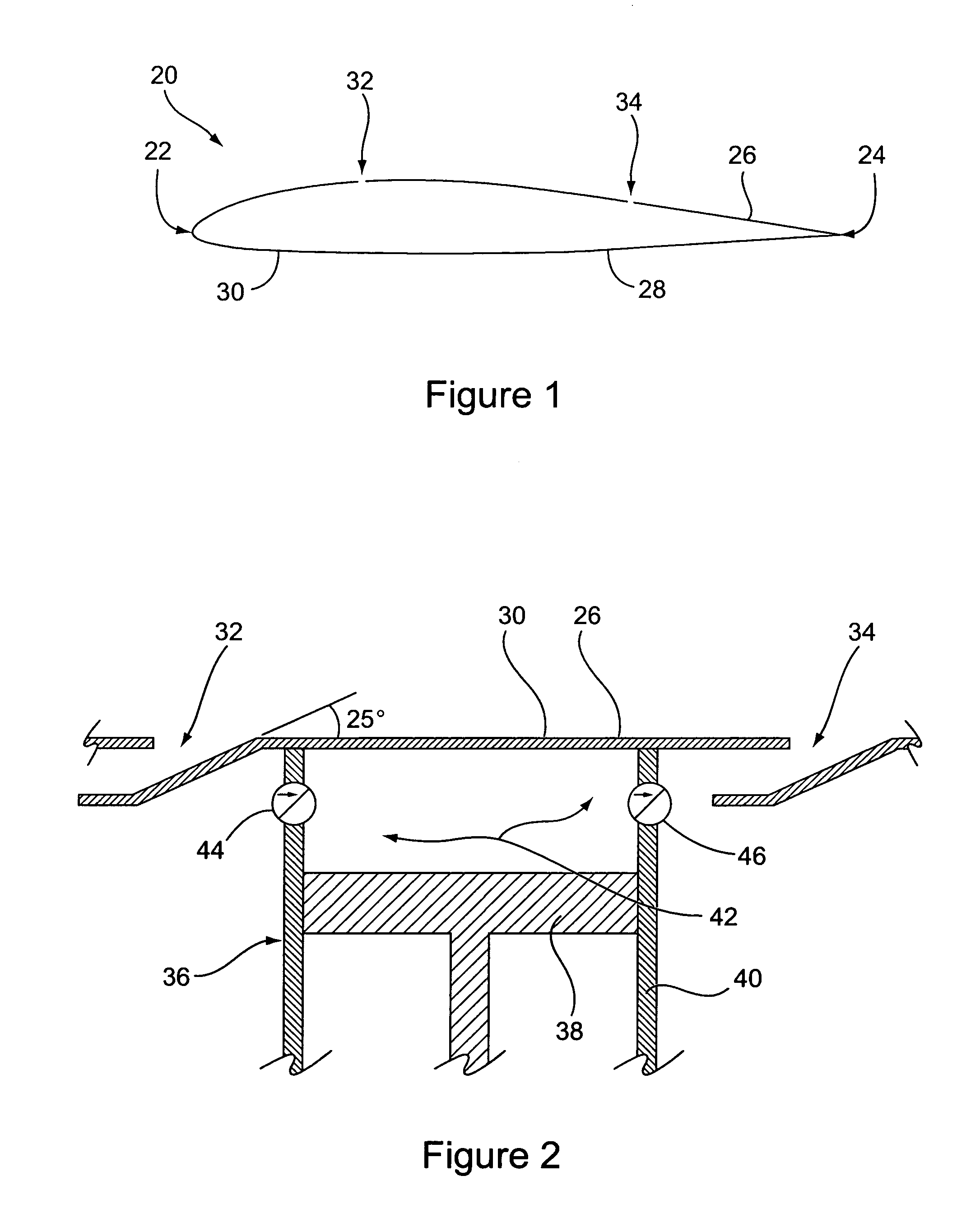
[0014]For purposes of testing the preferred method of practicing the invention, a 12% thick VR-7 airfoil having a 4% tailing edge tab was utilized. As shown in FIG. 1, this airfoil 20 has a leading edge 22 and a trailing edge 24 that separate opposite top 26 and bottom 28 portions of the exterior surface 30 of the airfoil. The leading 22 and trailing 24 edges also define a chord length that extends therebetween. It should be appreciated that this particular airfoil 20 is merely an exemplary airfoil and that the invention can be utilized on various types of airfoils, with or without movable control surfaces such a flaps. Moreover, it should be appreciated that the invention can be utilized in connection with airfoils on various types of devices, including, but not limited to, fan blades, turbine blades, aircraft wings, and aircraft rotor blades.

[0015]The AFC technique of the present invention is of particular benefit in situations or conditions where premature separation of fluid flo...


PUM


Abstract

An active flow control device and method for improving the aerodynamic efficiency of airfoils. The device and method pertain to the application of hybrid intermittent suction or intake of low-energy boundary layer fluid into an airfoil through one or more inlet openings while also applying intermittent blowing or expulsion of fluid out of such an airfoil into the boundary layer through one or more outlet openings for the purpose of delaying or eliminating boundary layer separation.

Description

BACKGROUND OF THE INVENTION[0001]The aerodynamic performance, hence efficiency, of airfoils, rotor blades, wings, turbine / compressor blades, and windmill blades, is strongly dependent upon the lift-to-drag (L / D) ratio of such airfoils. To this end, active flow control (AFC) techniques have been utilized to increase the L / D ratio. These AFC techniques include providing ports and / or openings through the surface of such airfoils and applying steady blowing, steady suction, or alternating blowing and suction of fluid therefrom. Such AFC techniques have proven to be effective in increasing the lift coefficient of airfoils, decreasing their drag coefficient, or both in a manner that increases the overall L / D ratio of the airfoils, and thereby increasing their aerodynamic efficiency.[0002]AFC techniques are particularly advantageous in situations where large flow separations over such airfoils would otherwise exist. Such situations frequently occur when airfoils are orientated at high angl...

Claims


Application Information

Patent Timeline
Patent Type & Authority Patents(United States)
IPC IPC(8): B64C21/00B64C21/02
CPCB64C21/025B64C2230/18Y02T50/166Y02T50/10
Inventor HASSAN, AHMED A.JANAKIRAM, RAM D.CERCHIE, DINO A.
Owner THE BOEING CO
Why Eureka
Try Eureka