Connecting structure for vacuum pump

Inactive Publication Date: 2005-05-31
EDWARDS JAPAN
View PDF11 Cites 9 Cited by
  • Summary
  • Abstract
  • Description
  • Claims
  • Application Information

AI Technical Summary

Benefits of technology

[0018]Since the electrical insulating portion is provided to the connecting piping member such as the damper and the valve, electrical insulating properties c

Problems solved by technology

This may lead to a troublesome situation where electrical noise generated by electric equipment such as a mot

Method used


Image

  • Connecting structure for vacuum pump
  • Connecting structure for vacuum pump
  • Connecting structure for vacuum pump

Examples


first embodiment

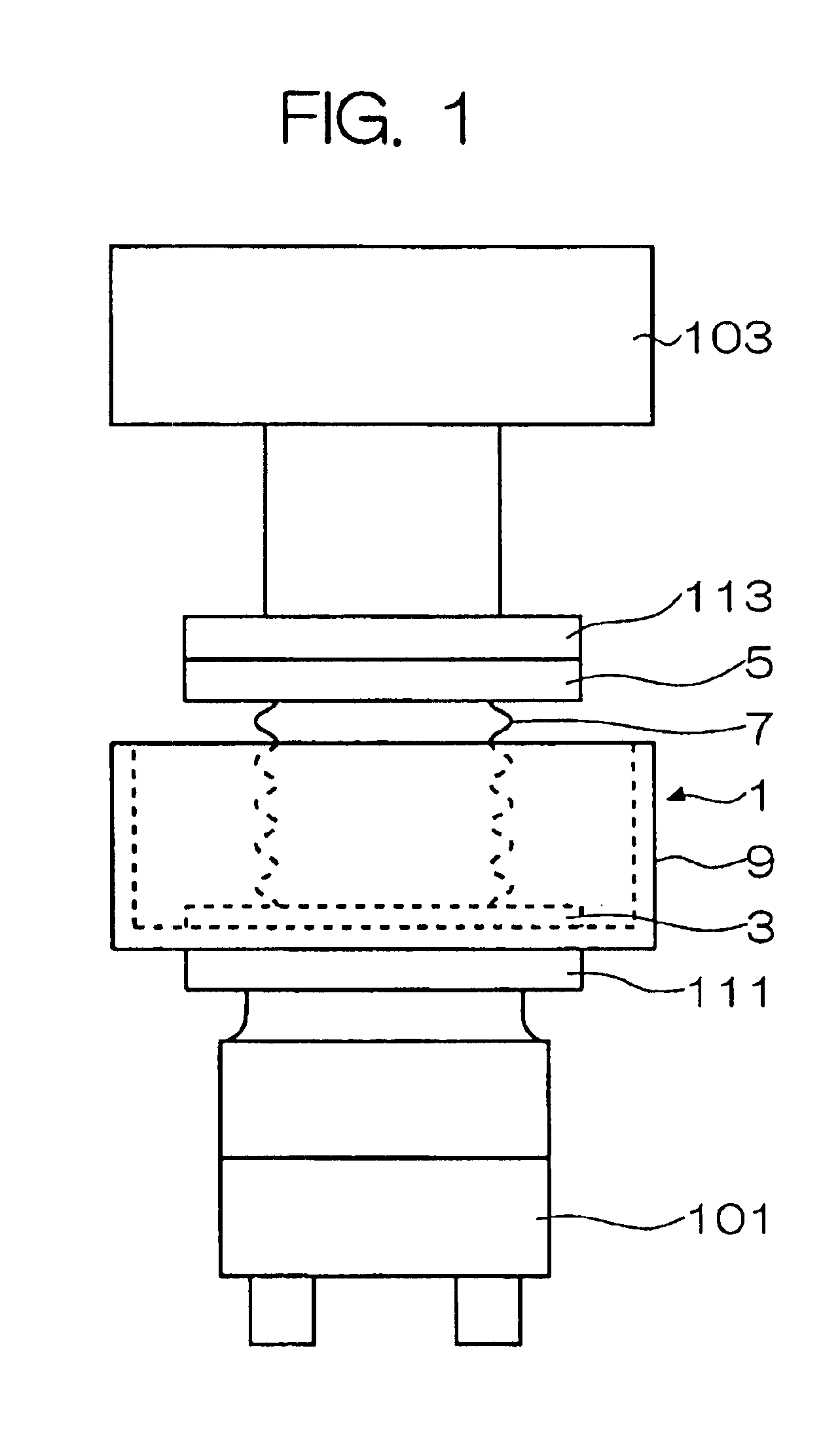
[0026]Embodiments of the present invention will be described hereinbelow. FIG. 1 is a side elevation view of a connecting structure for a vacuum pump in accordance with the present invention. Note that like reference numerals are given to denote portions that are identical to those of FIG. 6, and an explanation thereof is omitted here.

[0027]Referring to FIG. 1, a vacuum pump 101 such as a turbo molecular pump is connected through piping to a vacuum chamber 103 in a hanging fashion, with a damper 1 for absorbing mechanical vibrations and providing electrical insulation being interposedly disposed between a suction port thereof and the vacuum chamber 103 being a measurement chamber.

[0028]The damper 1 has flanges 3 and 5 arranged on its both ends, and a bellows 7 capable of absorbing mechanical vibrations is provided between the flanges 3 and 5. In addition to being configured to absorb mechanical vibrations, the bellows 7 is formed as an electrical insulating portion made up of an ele...

second embodiment

[0047]Next, description will be made of the present invention.

[0048]FIG. 5 is a side elevation view of a connecting structure for the vacuum pump 101 in accordance with a second embodiment of the present invention. Note that like reference numerals are given to denote portions that are identical to those of FIGS. 1 and 6, and an explanation thereof are omitted here.

[0049]Referring to FIG. 5, a damper 105 and a valve 11 are arranged in series through piping connection between a vacuum pump 101 and a vacuum chamber 103 being a measurement chamber. A flange 17 at the upper end of the valve 11 is coupled with a flange 113 of the vacuum chamber 103 being a measurement chamber. Also, a flange 15 at the lower end of the valve 11 is coupled with a flange 109 at the upper end of the damper 105.

[0050]The valve 11 is a pressure control valve for controlling a pressure within the vacuum chamber 103 on the measurement chamber side. The valve 11 is constructed such that it constitutes an electric...


PUM


Abstract

Provided is a connecting structure for a vacuum pump, which can block propagation of electrical noise, generated by a main body of the vacuum pump. Between both ends of a connection piping for connecting the vacuum pump to a vacuum chamber of an apparatus to be connected with and evacuated by the vacuum pump, there is interposedly provided an electrical insulating portion formed of an insulating material so as to provide electrical insulation therebetween. The electrical insulation portion may be provided to a connection piping member such as a damper (or a valve depending on the connection arrangement) for absorbing mechanical vibrations.

Description

BACKGROUND OF THE INVENTION[0001]1. Field of the Invention[0002]The present invention relates to a connecting structure for connecting a vacuum pump. In particular, it relates to a connecting structure for a vacuum pump, which is capable of blocking propagation of electrical noise generated by a main body of the vacuum pump.[0003]2. Description of the Related Art[0004]A conventional connecting structure used for connecting a vacuum pump (hereinafter referred to as the “connecting structure for a vacuum pump) is shown in FIG. 6.[0005]Referring to FIG. 6, when a vacuum pump 101 is connected through connection piping to a measuring apparatus such as an electron microscope which requires a vibration-free environment to operate, a damper 105 as a vibration absorbing member is interposedly disposed within the connection piping. Electron microscope etc. are provided in a vacuum chamber 103 being a measurement chamber. The vacuum pump 101 is suspended from the vacuum chamber 103 with the da...

Claims


Application Information

Patent Timeline
IPC IPC(8): F04D19/00F04D19/04F04D29/66F04D29/60F04D29/02F04B37/16F04D29/00F04D29/42F04D29/44
CPCF04D19/04F04D29/668F04D29/601F04D29/00
Inventor ISHIKAWA, TAKAHARUYAMAUCHI, AKIRA
Owner EDWARDS JAPAN
Why Eureka
Try Eureka