Antenna array with at least one dipole-type emitter arrangement

A technology of antenna system and radiator, applied in the direction of antenna, resonant antenna, antenna parts, etc., can solve the problem of small bandwidth

Active Publication Date: 2019-03-01
TELEFON AB LM ERICSSON (PUBL)
View PDF22 Cites 4 Cited by
  • Summary
  • Abstract
  • Description
  • Claims
  • Application Information

AI Technical Summary

Problems solved by technology

[0011] A disadvantage of prior art radiator arrangements is that the

Method used


Image

  • Antenna array with at least one dipole-type emitter arrangement
  • Antenna array with at least one dipole-type emitter arrangement
  • Antenna array with at least one dipole-type emitter arrangement

Examples


Embodiment Construction

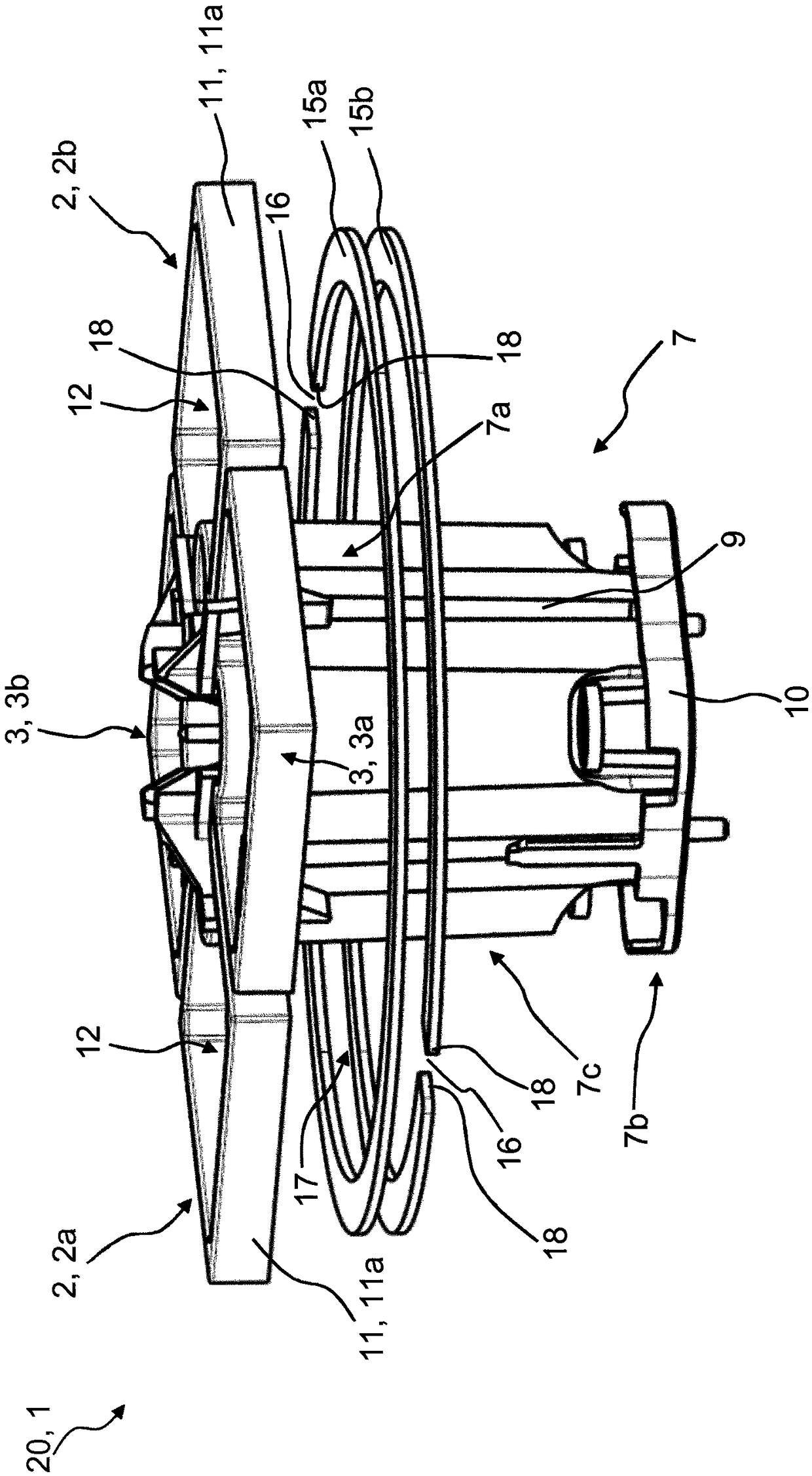
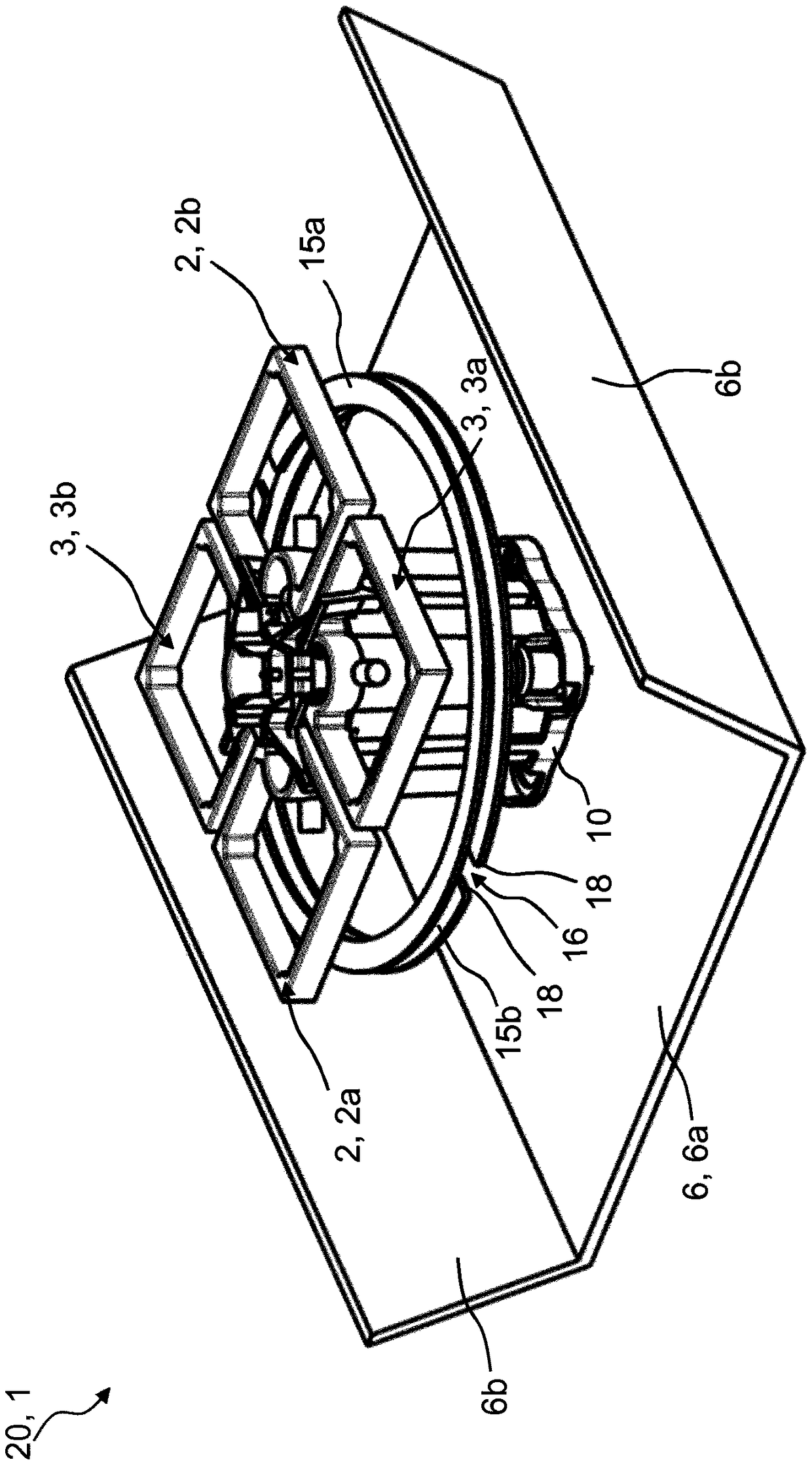
[0036] figure 1 , 2 and 4 show a spatial view of an antenna system 20 according to the invention comprising at least one dipole-shaped radiator arrangement 1 . The dipole-shaped radiator arrangement 1 comprises two pairs 2, 3 of radiator halves 2a, 2b, 3a, 3b. The two pairs of 2, 3 radiator halves 2a, 2b, 3a, 3b can be clearly seen especially from the top view of FIG. 7c, which shows an antenna system 20 with at least two dipole-shaped radiator arrangements 1 . The two pairs of 2, 3 radiator halves 2a, 2b or 3a, 3b are arranged rotated by 90° relative to each other, so that the dipole-shaped radiator arrangement 1 is in two mutually perpendicular polarization planes 4a, 4b (cf. Figure 7C ) to send and / or receive. The radiator halves 2 a , 2 b or 3 a , 3 b are aligned in a radiator plane 5 here. The radiator plane 5 is for example at Figure 7B , which shows a side view of an antenna system 20 with at least two dipole-shaped radiator arrangements 1 . The radiator halves...


PUM


Abstract

An antenna array (20) with at least one dipole-type emitter arrangement (1), wherein the at least one dipole-type emitter arrangement (1) comprises two pairs (2, 3) of emitter halves (2a, 2b, 3a, 3b),which transmit and/or receive on two polarization planes (4a, 4b) that are perpendicular to one another. The emitter halves (2a, 2b, 3a, 3b) can be or are arranged on an emitter plane (5) at a distance from a reflector (6) and run parallel to said reflector. Two electrically conductive partial circumferential frames (15a, 15b, 15c) are provided, which are disposed between the emitter plane (5) and the reflector (6) at a distance from one another, wherein the at least two electrically conductive partial circumferential frames (15a, 15b, 15c) define one opening (17). The at least two partial circumferential frames (15a, 15b, 15c) are oriented parallel to the emitter plane (5). Each of the two partial circumferential frames (15a, 15b, 15c) comprises at least one gap (16), which extends through the entire width of the partial circumferential frame (15a, 15b, 15c), so that each partial circumferential frame (15a, 15b, 15c) comprises at least two ends.

Description

technical field [0001] The invention relates to an antenna system with at least one dipole-shaped radiator arrangement according to the preamble of claim 1 . Background technique [0002] Dipole radiators are known, for example, from the prior publications DE19722742A and DE19627015A. In this case, such a dipole radiator can have a conventional dipole structure or be formed, for example, from crossed dipoles or square dipoles or the like. [0003] So-called vector dipoles are known, for example, from the prior publication WO 00 / 39894 A1. Its structure appears to be comparable to a square dipole. But due to the special design and the special feeding of the dipole radiator according to this prior publication, this dipole radiator acts like a crossed dipole, which radiates in two mutually perpendicular polarization planes . From a structural point of view, vector dipoles are more likely to be square, especially based on their outer contour design. [0004] Another embodime...

Claims


Application Information

Patent Timeline
IPC IPC(8): H01Q1/24H01Q9/28H01Q19/30H01Q5/385
CPCH01Q1/246H01Q9/28H01Q19/30H01Q25/001H01Q5/385H01Q1/241
Inventor M·奎特
Owner TELEFON AB LM ERICSSON (PUBL)
Why Eureka
Try Eureka