Electrostatic air cleaner

a technology of air cleaner and vacuum cleaner, which is applied in the direction of external electric electrostatic seperator, transportable electrostatic unit, electrode construction, etc., can solve the problems of difficult cleaning and relative large structure, and achieve the effects of moderate voltage level, easy manufacturing, and small structur

Inactive Publication Date: 2005-05-31
HELEN OF TROY LIMITED
View PDF27 Cites 49 Cited by
  • Summary
  • Abstract
  • Description
  • Claims
  • Application Information

AI Technical Summary

Benefits of technology

[0004]In one illustrative embodiment, the present invention provides an electrostatic air cleaner t

Problems solved by technology

While effective, this arrangement necessitated relatively large

Method used


Image

  • Electrostatic air cleaner
  • Electrostatic air cleaner
  • Electrostatic air cleaner

Examples


Embodiment Construction

[0023]Various embodiments in accordance with the invention may be used to clean particulate matter from various gasses or gas mixtures. In certain embodiments, air cleaners according to the invention may be used in a house, garage, office, or similar environment to clean air. Certain embodiments also have the benefit of a small size which allows them to not take up much space in the room or other environment being cleaned. Air cleaners according to the invention may also be sized to be portable, i.e., carried by hand and selectively placed within a space the air of which is desired to be cleaned.

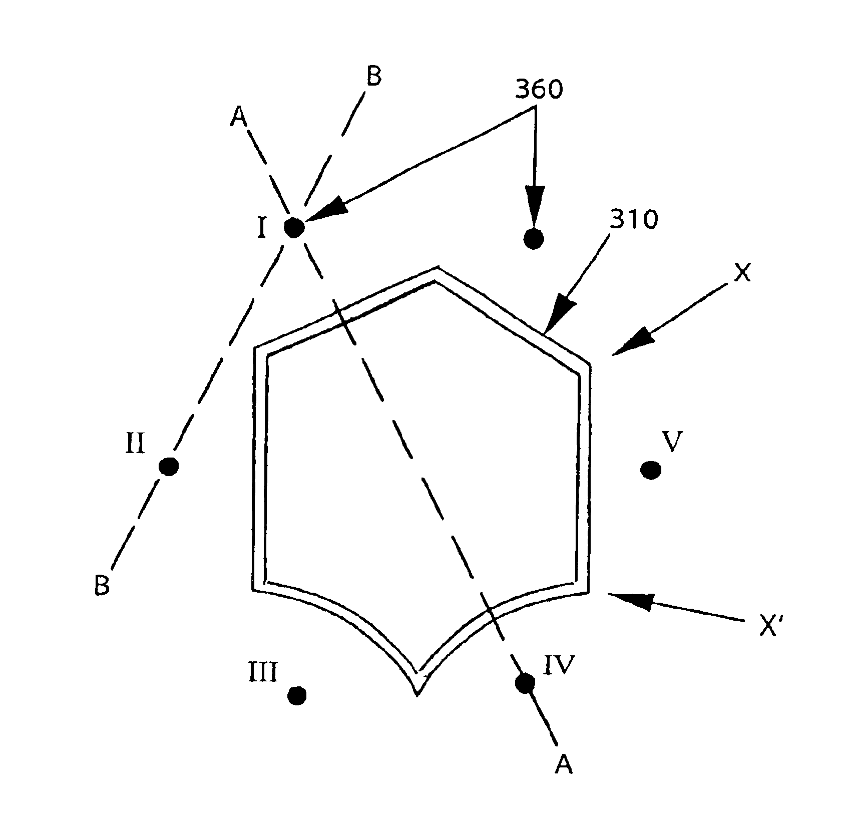
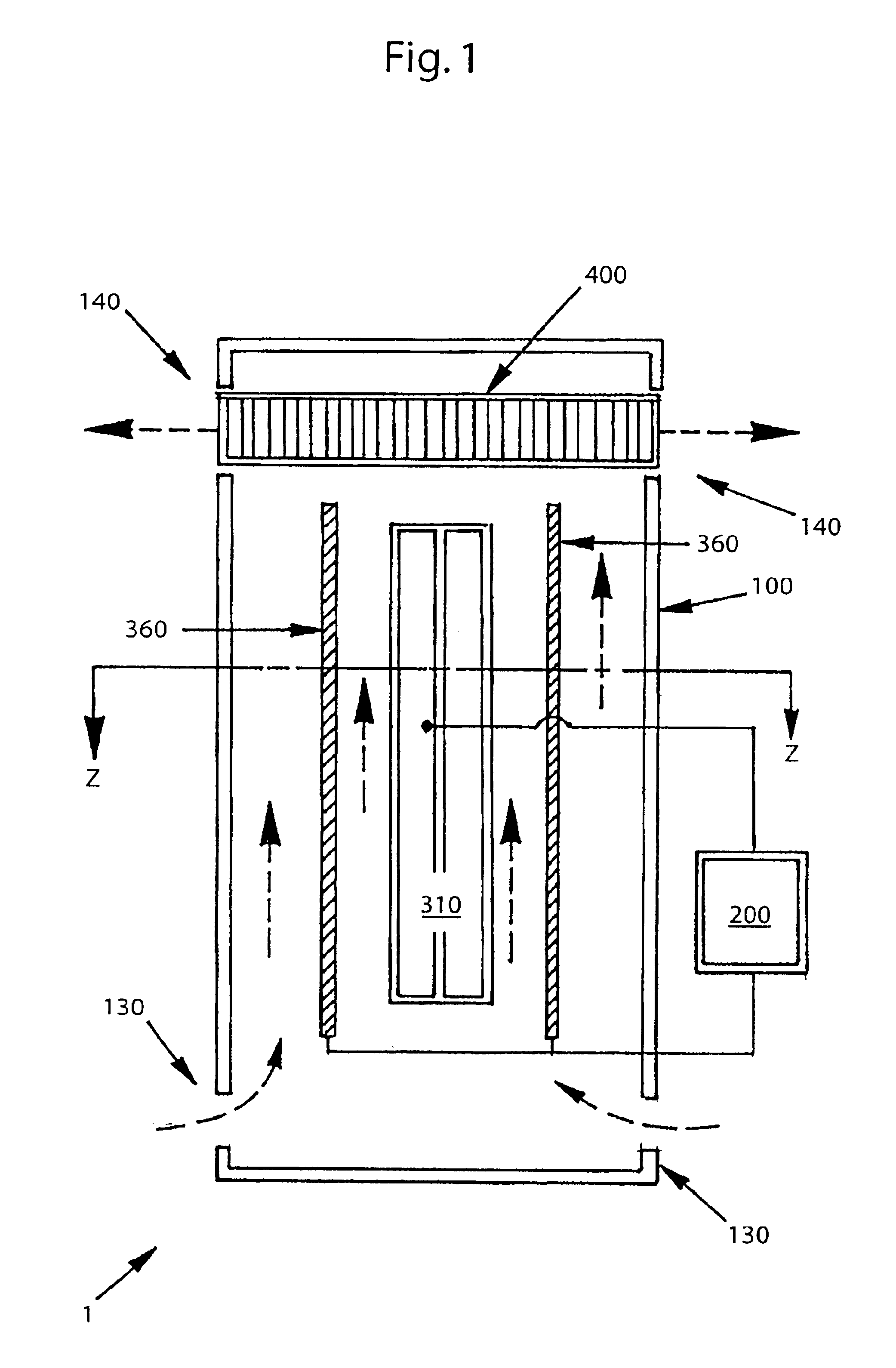
[0024]FIG. 1 shows a schematic view of an illustrative embodiment of an air cleaner 1 in accordance with the invention. In this embodiment, the air cleaner 1 has a housing 100 that includes air inlets 130 and air outlets 140, power supply circuitry 200, a collector electrode 310 connected to a first output of the power supply circuitry 200, a plurality of discharge electrodes 360 connected t...


PUM


Abstract

An air cleaner electrode assembly includes an elongated collector electrode and a plurality of elongated discharge electrodes arranged around the collector electrode. A fan may move air in a direction parallel to a length of the electrodes. The collector electrode may have a plurality of distinct faces where at least one discharge electrode is associated with a corresponding face. A cleaning shuttle may be configured to ride on and remove debris from the elongated electrodes. A voltage differential across the electrodes and the fan speed may be adjusted independently of each other.

Description

FIELD OF THE INVENTION[0001]This invention relates to electrostatic air cleaners.BACKGROUND OF THE INVENTION[0002]Electrostatic precipitation is a widely used method for cleaning gasses, having long been used in large scale industrial applications. The fundamental design of electrostatic precipitators remained largely unchanged for years. In a typical application, seen, for example, in U.S. Pat. No. 1,204,907, a high voltage electrode was placed in the center of a grounded tube. The high voltage caused corona discharge between the discharge electrode and the grounded tube which imparted an electrostatic charge to particles in a gas between the discharge electrode and the grounded tube. The charged particles were then precipitated electrostatically onto the surface of the grounded tube, resulting in cleaner gas. While effective, this arrangement necessitated relatively large structures and had the disadvantage of being difficult to clean.[0003]Recent efforts have been directed at ada...

Claims


Application Information

Patent Timeline
IPC IPC(8): B03C3/00B03C3/32B03C3/74B03C3/08B03C3/45B03C3/04B03C3/34
CPCB03C3/08B03C3/32B03C3/743B03C3/45Y10S55/38B03C2201/14
Inventor GATCHELL, STEPHEN M.WANG, CHI-HSIANG
Owner HELEN OF TROY LIMITED
Why Eureka
Try Eureka