Stall detection circuit and method

a detection circuit and a technology of stall detection, applied in the direction of dynamo-electric converter control, dynamo-electric machine testing, instruments, etc., can solve the problem of difficult to discern if the rotor has been blocked or rotated in the wrong direction

Inactive Publication Date: 2005-05-31
SAIA BURGESS AUTOMOTIVE
View PDF13 Cites 65 Cited by
  • Summary
  • Abstract
  • Description
  • Claims
  • Application Information

AI Technical Summary

Benefits of technology

[0009]In view of the foregoing, one object of the present invention is to avoid the difficulties associated with the failure to recognize a motor stall condition.
[0010]Another object of the present invention is to provide a circuit that is able to detect changes in back EMF as generated by different rotor conditions to determine if the rotor is in normal running mode or has been blocked or rotated incorrectly.
[0011]A further object of the present invention is to provide an improved H-bridge circuit construction that includes an additional current flow path to clarify back EMF detection.
[0012]It is yet another object of the present invention to provide a circuit that is not complex in structure and may be implemented within existing circuits at low cost but yet used to efficiently monitor rotor conditions.

Problems solved by technology

It is therefore difficult to discern if the rotor has been blocked or rotated in the wrong direction.

Method used


Image

  • Stall detection circuit and method
  • Stall detection circuit and method
  • Stall detection circuit and method

Examples


Embodiment Construction

[0023]In describing a preferred embodiment of the invention illustrated in the drawings, specific terminology will be resorted to for the sake of clarity. However, the invention is not intended to be limited to the specific terms so selected, and it is to be understood that each specific term includes all technical equivalents which operate in a similar manner to accomplish a similar purpose.

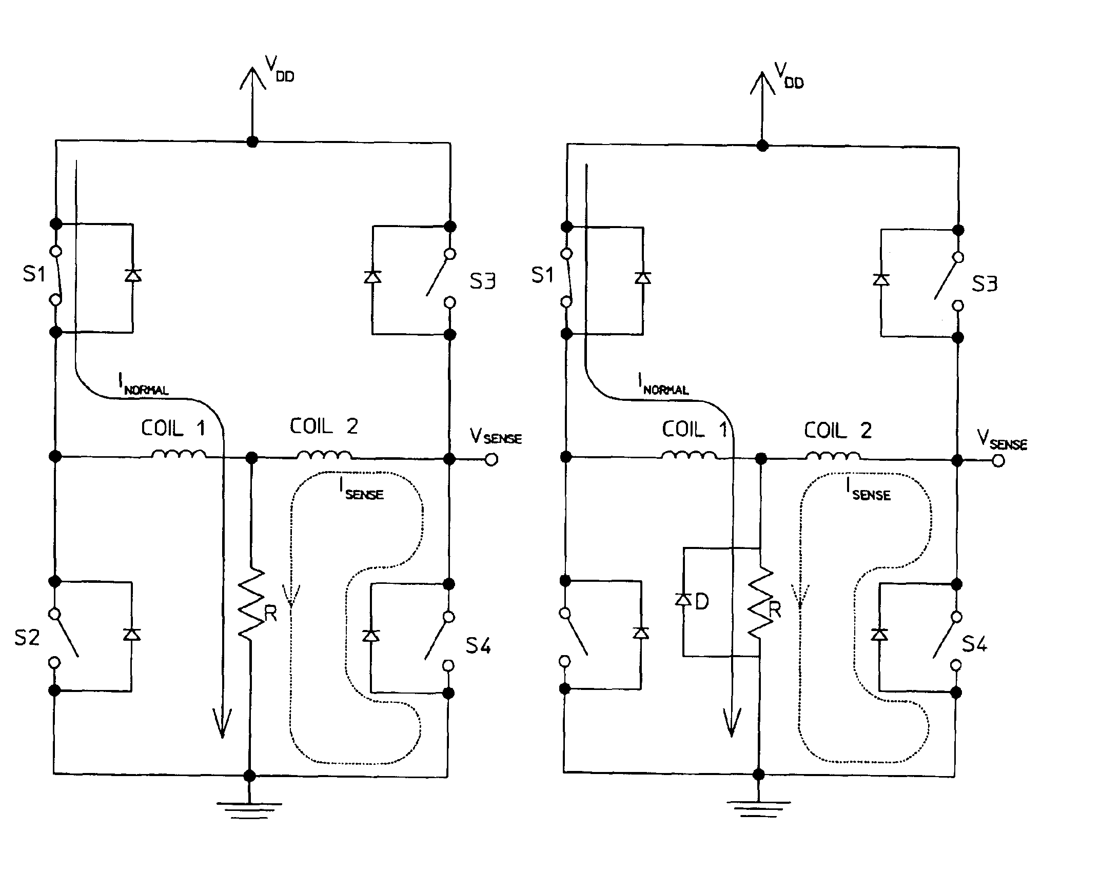
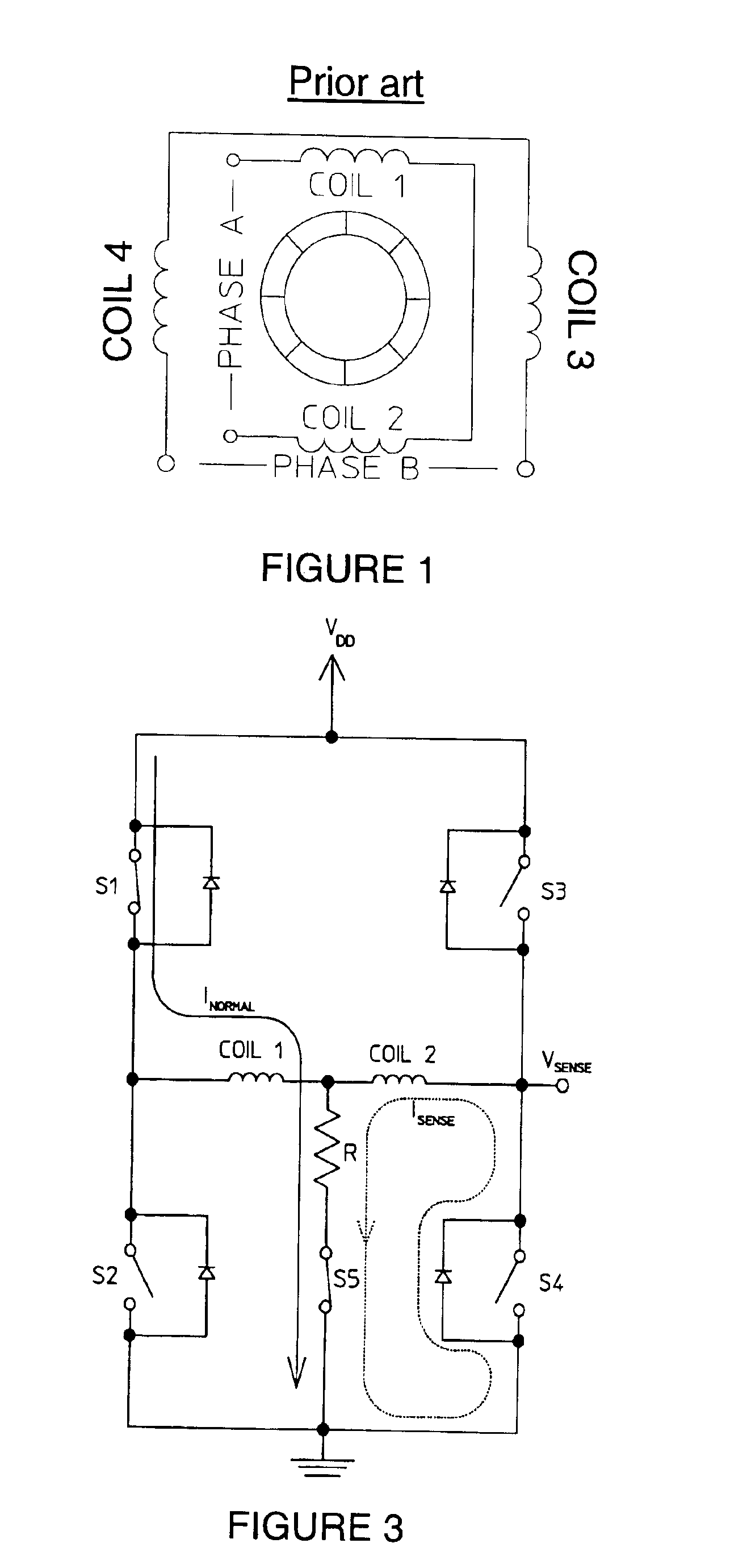
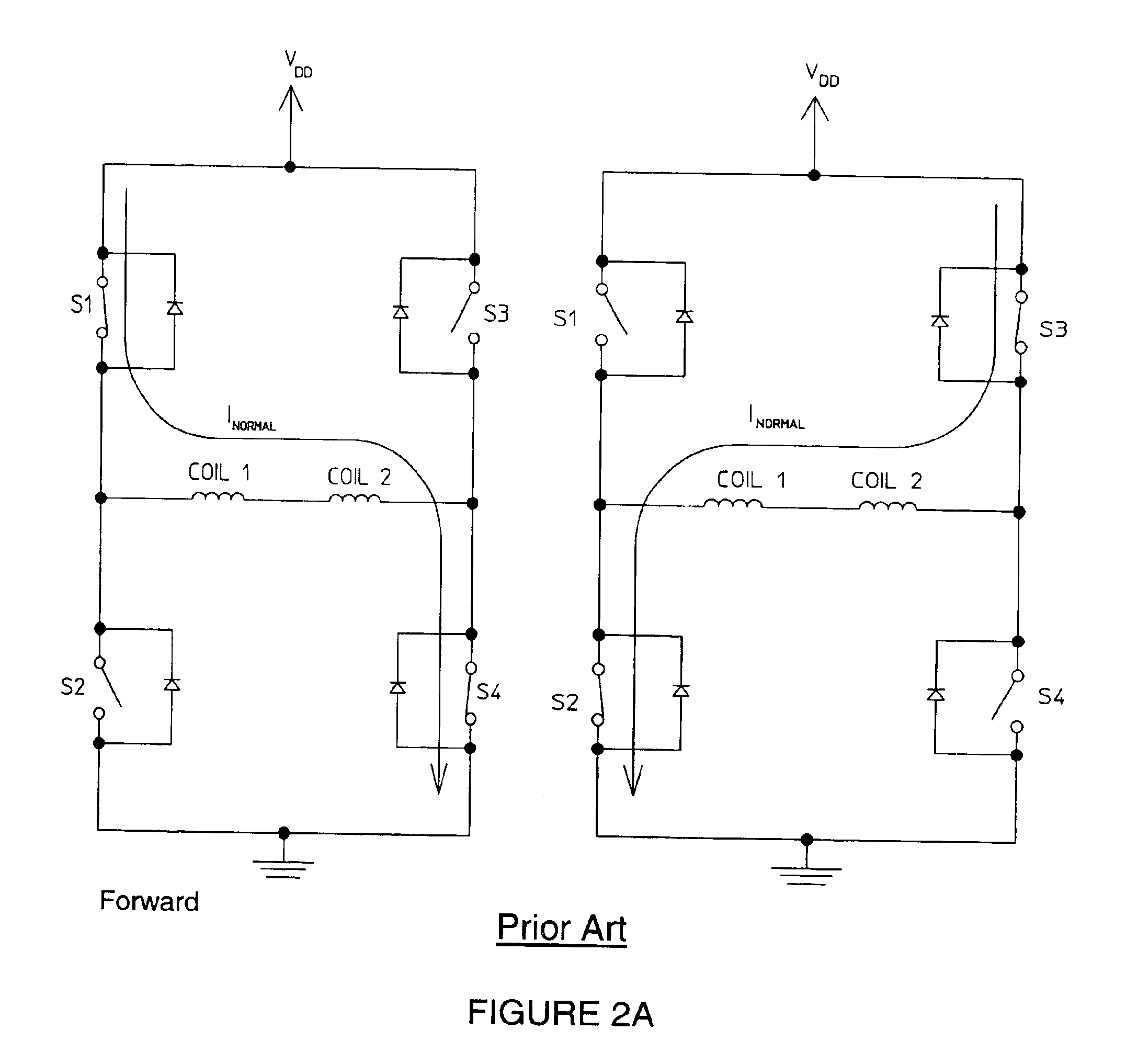
[0024]The present invention is directed to a stall detection circuit such as that shown representatively in FIG. 3. As with the conventional circuit shown in FIGS. 2A-2C, one H-bridge driver powers each of the two steps of the four-coil stepper motor operating in two-phase-on mode. During a first step, switches S1 and S4 are closed, and during a second step, switches S3 and S2 are closed. The sequence of the steps changes according to whether the motor is in forward or reverse operating condition, as shown in FIGS. 2A and 2B, respectively.

[0025]According to the present invention, the stall detec...


PUM


Abstract

A stall detection circuit and method for a stepper motor. The circuit has an H-bridge configuration with an additional circuit pathway to ground being connected at a point between two center windings. During the transition between step sequences, the circuit employs a monitoring phase in which the previously active low side driver is turned off such that current passes through only the first winding and then is diverted to ground via the additional pathway. While the phase voltage is thus momentarily extinguished, the second coil is used to monitor the motor's back EMF, from which it can be determined whether the rotor is in a normal running mode, a stall, or a reverse condition.

Description

BACKGROUND OF THE INVENTION[0001]1. Field of the Invention[0002]The present invention is directed to the monitoring of motor operation and, more particularly, to a stall detection circuit for two-phase, four-coil stepper motors operating in two-phase-on mode.[0003]2. Description of the Related Art[0004]Two-phase, four-coil stepper motors include a permanent magnet rotor 10 with multiple pole pairs, namely having two stator phases made up of two coils connected in series in each phase, as shown in FIG. 1.[0005]Under typical operation, one H-bridge driver powers each phase. As shown in FIGS. 2A-2C, the standard H-bridge circuit includes a first path having a first switch S1 connected in series with a second switch S2 and, in parallel therewith, a second path having a third switch S3 in connected in series with a fourth switch S4. A pair of coils, coil 1 and coil 2, are connected in series on a branch between a node on the first path between the first and second switches, and a node on...

Claims


Application Information

Patent Timeline
Patent Type & Authority Patents(United States)
IPC IPC(8): G01R31/02G01R31/06G01R31/34H02P8/36
CPCH02P8/36
Inventor BUI, TANH M.CHOW, DACON T.
Owner SAIA BURGESS AUTOMOTIVE
Why Eureka
Try Eureka