Light deflecting method and apparatus efficiently using a floating mirror

a floating mirror and light deflector technology, applied in the field of light deflector methods and apparatuses, can solve the problems of difficult stabilization of light reflecting members, late response speed, and deformation of mechanical strength of hinges of twisted portions in usage, so as to reduce mechanical stress and improve light deflection

Inactive Publication Date: 2005-05-31
RICOH KK
View PDF24 Cites 282 Cited by
  • Summary
  • Abstract
  • Description
  • Claims
  • Application Information

AI Technical Summary

Benefits of technology

[0013]In view of the foregoing, it is an object of the present invention to provide a novel method of light deflecting which reduces a mechanical stress and performs a superior light deflection.

Problems solved by technology

However, in the light deflecting device and the digital micro-mirror device having the twisted-type light reflecting member or the cantilever-like light reflecting member, the light reflecting member is difficult to be stably held and a response speed is late.
Also, in the above-mentioned digital micro-mirror device having the twisted-type light reflecting member, a hinge of the twisted portion may degrade its mechanical strength in a usage over an extended period of time.
Further, a light deflecting device for switching light by driving a diffraction grating with an electrostatic attraction force limits an allowable wavelength of an input light ray.
This structure is relatively complex and the mirror plate is actually not held in a completely free condition.
Due to this structure, in which the mirror plate is made of a magnetic metal, the magnet is arranged under the mirror bed, and magnetic yokes are arranged around the mirror bed, it is very difficult to make the two-axis movable mirror and the apparatus using the mirror through a micromachining process.
In addition, the two-axis movable mirror and the apparatus using the mirror may emit magnetic force and the environments for these apparatuses may be limited.

Method used


Image

  • Light deflecting method and apparatus efficiently using a floating mirror
  • Light deflecting method and apparatus efficiently using a floating mirror
  • Light deflecting method and apparatus efficiently using a floating mirror

Examples


Embodiment Construction

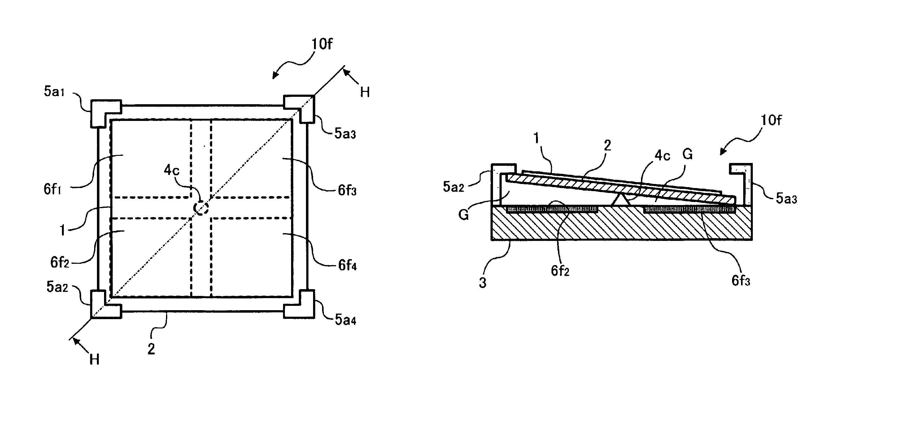
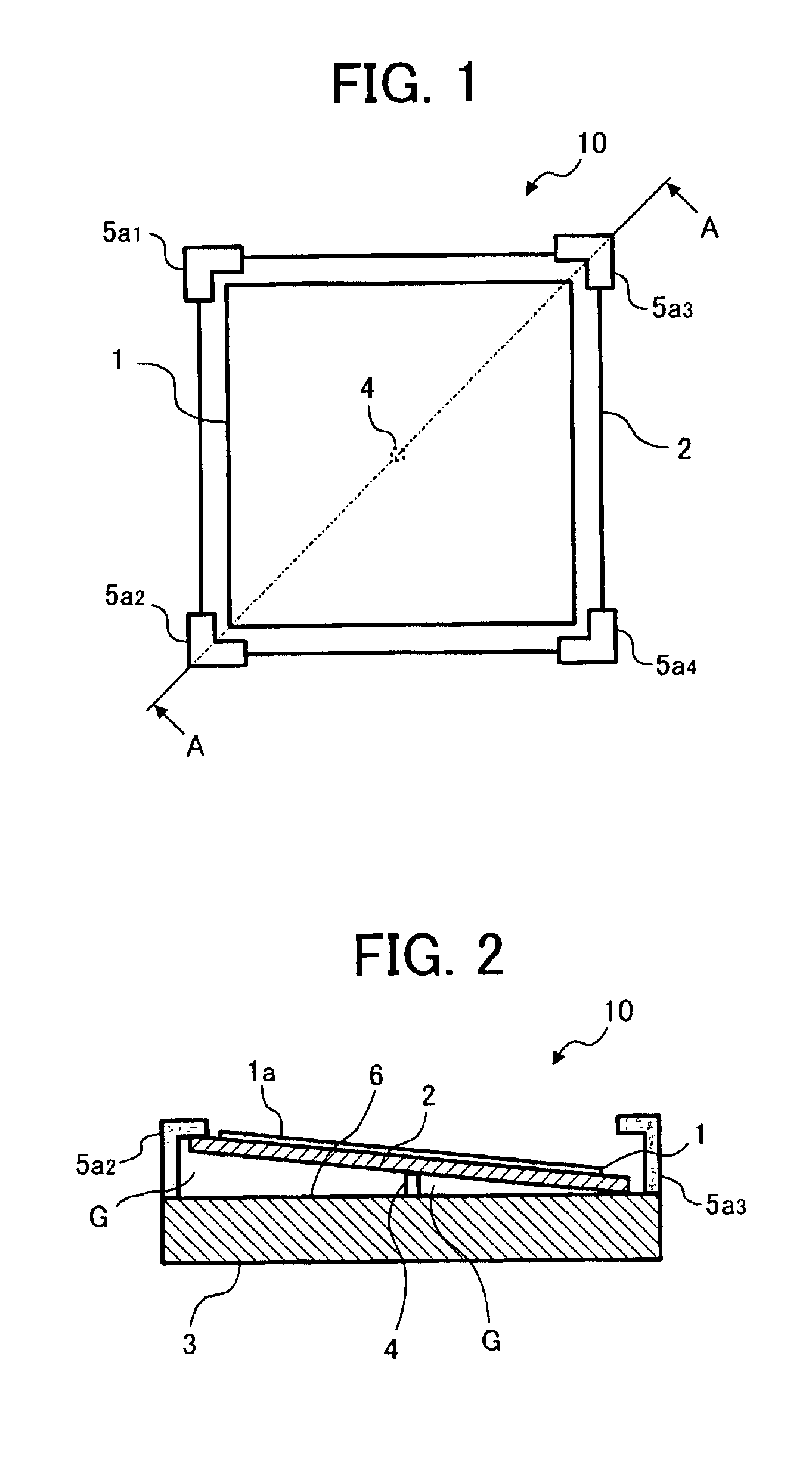
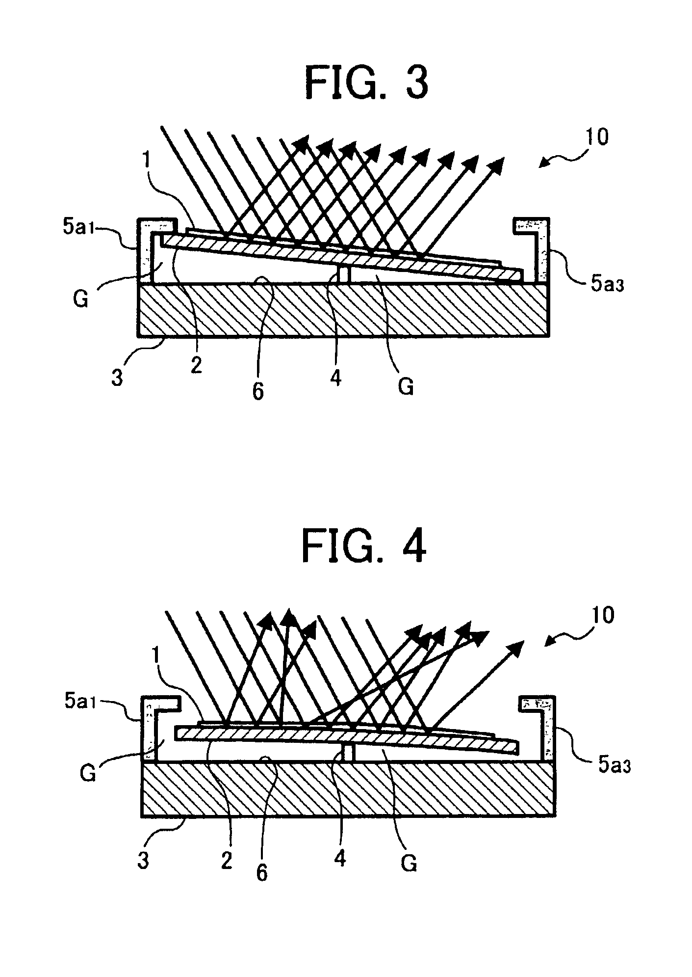
[0086]In describing preferred embodiments illustrated in the drawings, specific terminology is employed for the sake of clarity. However, the disclosure of this patent specification is not intended to be limited to the specific terminology so selected and it is to be understood that each specific element includes all technical equivalents that operate in a similar manner. Referring now to the drawings, wherein like reference numerals designate identical or corresponding parts throughout the several views, particularly to FIGS. 1, a description is made for a light deflecting apparatus 10 according to a preferred embodiment of the present invention. FIG. 1 is a plane view of the light deflecting apparatus 10, and FIG. 2 is a cross-section view taken on line A—A of FIG.1. The light deflecting apparatus 10 deflects input light into a signal axial reflective direction or two axial reflective directions. As shown in FIGS. 1 and 2, the light deflecting apparatus 10 includes a reflecting me...


PUM


Abstract

Method of deflecting light includes the steps of providing a substrate and forming a supporting member on the substrate. Next forming step forms electrodes at predetermined positions on the substrate. Next forming step forms a plate-like-shaped thin film member including light reflecting means. Placing step places the plate-like-shaped thin film member on the supporting member so that an opposite surface thereof faces the electrodes. Forming step forms space regulating members on edges of the substrate for regulating a space formed above the substrate in which the plate-like-shaped thin film member is freely movable. Applying step applies predetermined voltages to the electrodes to change a tilt direction of the plate-like-shaped thin film member in accordance with the voltages applied to deflect the input light in an arbitrary direction. Disclosure also describes light deflecting apparatuses, light deflecting array apparatuses, image forming apparatuses, image projection display apparatuses, and optical data transmission apparatuses.

Description

BACKGROUND OF THE INVENTION[0001]1. Field of the Invention[0002]The present invention relates to a method and apparatus for light deflecting, and more particularly to a method and apparatus for light deflecting capable of efficiently moving a floating mirror with an electrostatic attraction force.[0003]2. Discussion of the Background[0004]Conventionally, a light deflecting device and a light deflecting system using the light deflecting device are known, generating an electrostatic attraction force to bend a cantilever-like light reflecting member to change a reflection direction relative to input light rays. This apparatus is described in Japanese Patent No. 2,941,952, Japanese Patent No. 3,016871, Japanese Laid-Open Patent Application Publication No. 10-510374, “Applied Physics Letters,” 1977, vol. 31, No. 8, pp521-pp523, by K. E. Petersen, and “Optics Letters,” vol. 7, No. 9, pp688-pp690 by D. M. Bloom.[0005]Further, an image forming apparatus is also known, employing a light defl...

Claims


Application Information

Patent Timeline
Patent Type & Authority Patents(United States)
IPC IPC(8): G02B26/08
CPCG02B26/0841G02B6/3518Y10S359/90G02B6/357G02B6/3584G02B6/3556
Inventor NANJYO, TAKESHIKATOH, SEIICHIOHTAKA, KOUICHI
Owner RICOH KK
Why Eureka
Try Eureka