Electronic timepiece

a technology of electronic timepieces and timepieces, applied in the field of electronic timepieces, can solve the problems of not being able to dislocate or remove insulation components in the vicinity, and achieve the effect of reducing costs and facilitating assembly

Inactive Publication Date: 2005-05-31
SEIKO EPSON CORP
View PDF8 Cites 13 Cited by
  • Summary
  • Abstract
  • Description
  • Claims
  • Application Information

AI Technical Summary

Benefits of technology

[0016]It is an object of the present invention to provide an electronic timepiece that can insulate a power supply side from other conductive parts and guide an hour wheel (time-display wheel) by one kind of a member, make an assembly job easy and reduce cost.

Problems solved by technology

Further, there is not a possibility that the insulation member is dislocated or removed in the vicinity of the electrodes because it can be fixed in such a manner that it is attached by being fitted on the shaft of the hour wheel.

Method used


Image

  • Electronic timepiece
  • Electronic timepiece
  • Electronic timepiece

Examples


first embodiment

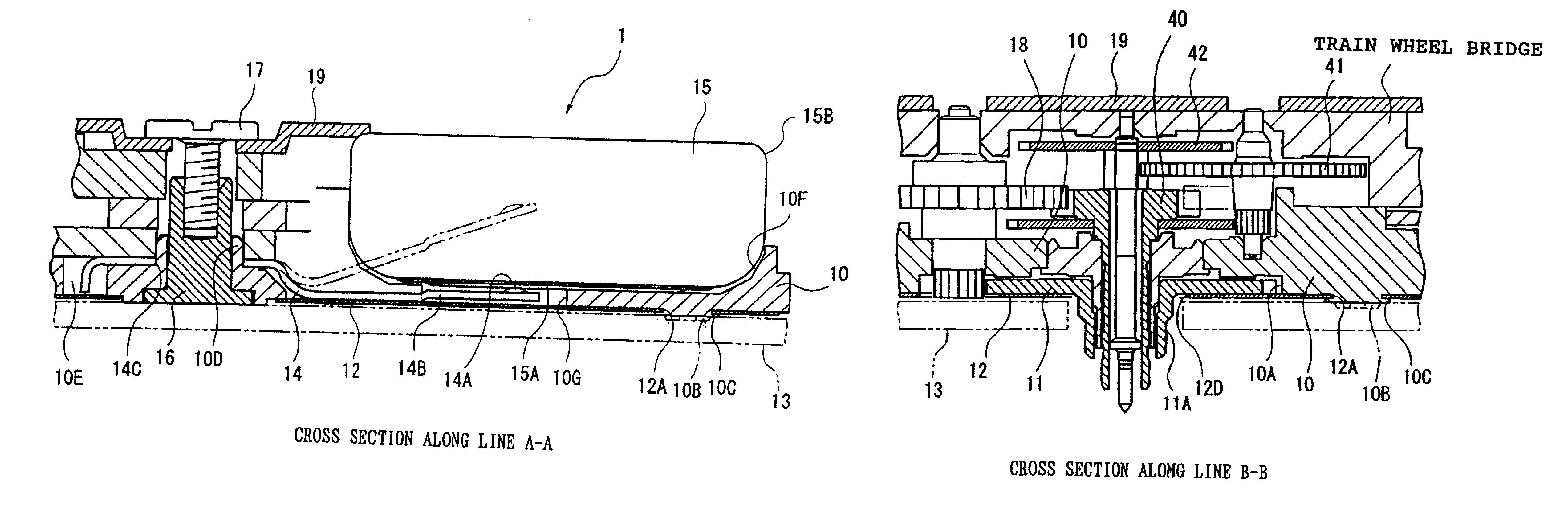
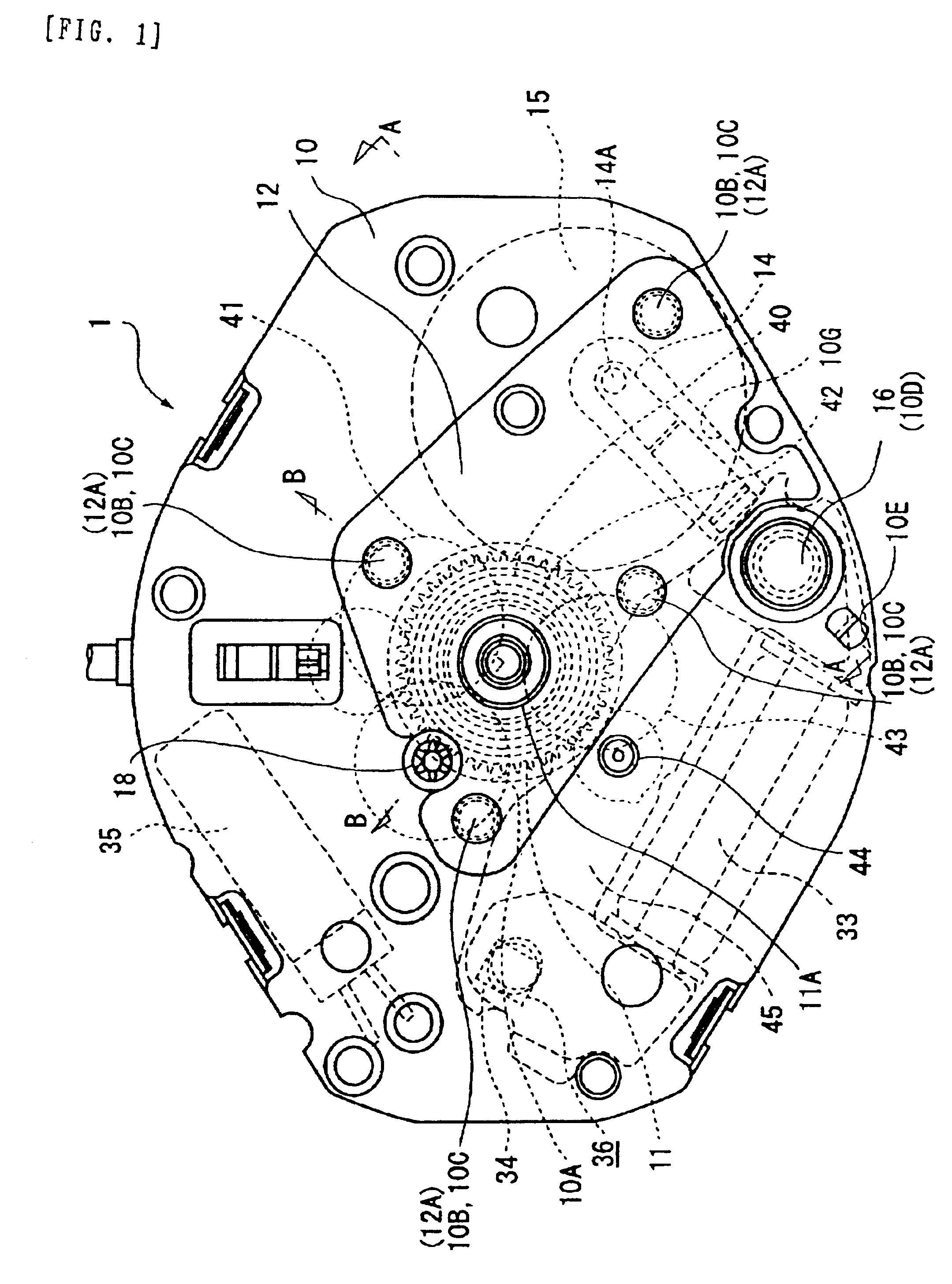
[0062]FIGS. 1 to 4 show an electronic timepiece of a

[0063]An insulation sheet 12 (FIGS. 1-4) acting as an insulation member in electronic timepiece 1 prevents an electric short-circuit between an electrode (such as the negative power rail terminal 14 (FIGS. 1 and 3) in contact with a pole of the power supply (15 FIGS. 1 and 3)) and a member (such as dial plate 13 (FIGS. 2-4) composed of, for example, metal or some other electrically conductive material) tied to a ground potential. Dial plate 13 includes guides for an hour wheel 11 (FIGS. 1 and 4). To mitigate the effects of an electric short-circuit, the negative pole 15A (FIG. 3) of power supply 15 (which acts as a power source) provides the driving supply voltage for a driving-controlled circuit 36 (FIG. 1). The other side of the power supply 15, i.e. the positive pole 15B (FIG. 3), functions as a reference ground and is coupled to dial plate 13, or the like. Further, the positive pole 15B of power supply 15, which is at least par...

second embodiment

[0098]Next, the present invention will be described based on FIG. 5.

[0099]In the present second embodiment, the entire timepiece movement is covered with an insulation sheet, whereas by contrast in the first embodiment, only the vicinity of the power supply 15 and the hour wheel 11 is flatly covered by insulation sheet 12. Elements in the present second embodiment similar to those of the first embodiment are identified by similar reference characters, and are described above.

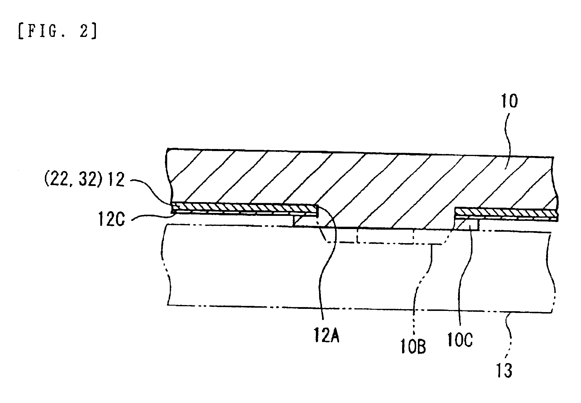
[0100]In the present second embodiment, an insulation sheet 22 acting as an insulation member covers approximately the overall surface of main plate 10 on the side facing dial plate 13, except for a portion corresponding to the periphery of the hour-hand-attachment portion 11A of a hour wheel 11, portions corresponding to insertion holes 10H necessary to assemble leg inserting portions of dial plate 13, and the like, and portions corresponding to initial protrusions 10B. Accordingly, the initial protrusions 10B ...

third embodiment

[0103]Next, the present invention will be described based on FIGS. 6 and 7.

[0104]In the third embodiment, an insulation sheet fixed in position pins plastically deformed through force, as opposed to the first and second embodiments where the insulation sheet is fixed by the thermally, activated, plastic deformation of protrusions from main plate 10. Note that the insulation sheet 22 covers the timepiece movement in its entirety in a manner similar to that of the second embodiment. Also in this third embodiment, the same reference numerals as used in the above respective embodiments are used to denote the same parts, the description of the same parts is simplified, and only different portions will be described.

[0105]As shown in FIG. 7, insulation sheet 22 is fixed to the back surface of a main plate 10 by deformations in screw pins 23. Screw pins 23 are first inserted into main plate 10, and insulation sheet 22 is then placed on screw pins 23. A chisel is then used to hit into the ex...


PUM


Abstract

In an electronic timepiece 1 having a main plate 10, a drive circuit 36, a stepper motor 33, a train wheel, a dial plate, a power supply 15, and an insulation sheet 12, the insulation sheet 12 covers at least the vicinity of the power supply 15 as well functioning as a guide to position an hour wheel 11 in an axial direction. Since the insulation sheet 12 has a predetermined size, it is neither dislocated nor removed when it is attached, whereby the insulation sheet 12 can reliably perform insulation, and an assembly property is improved thereby. Further, the insulation sheet 12 can achieve the dual roles of insulation and assembly guide, which can reduce cost and ease an assembly job.

Description

BACKGROUND OF THE INVENTION[0001]1. Field of the Invention[0002]The present invention relates to an electronic timepiece such as a quartz timepiece, and the like.[0003]2. Description of the Related Art[0004]There are known conventional electronic timepieces, such as quartz timepieces, that use an electronic circuit to generate accurate, periodic electrical signals measure the passage of time and to display the time.[0005]Similarly to mechanical wristwatches in wristwatches that use these electronic timepieces, it is desirable to make a timepiece movement small and thin in size. However, the size of a power supply is determined from a relationship between the power consumption (usually in terms of electric current) of a timepiece and the capacity of the power supply to meet the timepiece's power requirements while satisfying an expected life span for the power supply. Accordingly at present, the thickness of the timepiece movement of an electronic timepiece is dominated by the thickn...

Claims


Application Information

Patent Timeline
Patent Type & Authority Patents(United States)
IPC IPC(8): G04C3/00G04C3/14H01L31/04
CPCG04C3/008
Inventor ITO, TOKIKO
Owner SEIKO EPSON CORP
Why Eureka
Try Eureka