Gas turbine engine with variable pressure ratio fan system

a gas turbine engine and variable pressure technology, applied in the field of aircraft gas turbine engines, can solve the problems of reducing the hub pressure ratio that supercharges the core, negating the improvement of specific fuel consumption, and reducing cycle efficiency, so as to achieve good specific fuel consumption, reduce power cruise operation, and high specific thrust

Inactive Publication Date: 2005-06-07
GENERAL ELECTRIC CO
View PDF19 Cites 86 Cited by
  • Summary
  • Abstract
  • Description
  • Claims
  • Application Information

AI Technical Summary

Benefits of technology

[0013]The aircraft gas turbine engine embodiments above can modulate bypass flow from a fan section around a core engine to the bypass stream while effectively operating at high fan hub and bypass stream pressure ratios to provide high specific thrust at takeoff and climb power settings and can operate at low bypass stream pressure ratios to provide good specific fuel consumption during reduced power cruise operation.

Problems solved by technology

Although a conventional fan can be made to operate at reduced pressure ratios (limited by choking of the flow within the blading), this will also reduce the hub pressure ratio that supercharges the core, thereby, reducing cycle efficiency and negating the improvements in specific fuel consumption.

Method used


Image

  • Gas turbine engine with variable pressure ratio fan system
  • Gas turbine engine with variable pressure ratio fan system
  • Gas turbine engine with variable pressure ratio fan system

Examples


Embodiment Construction

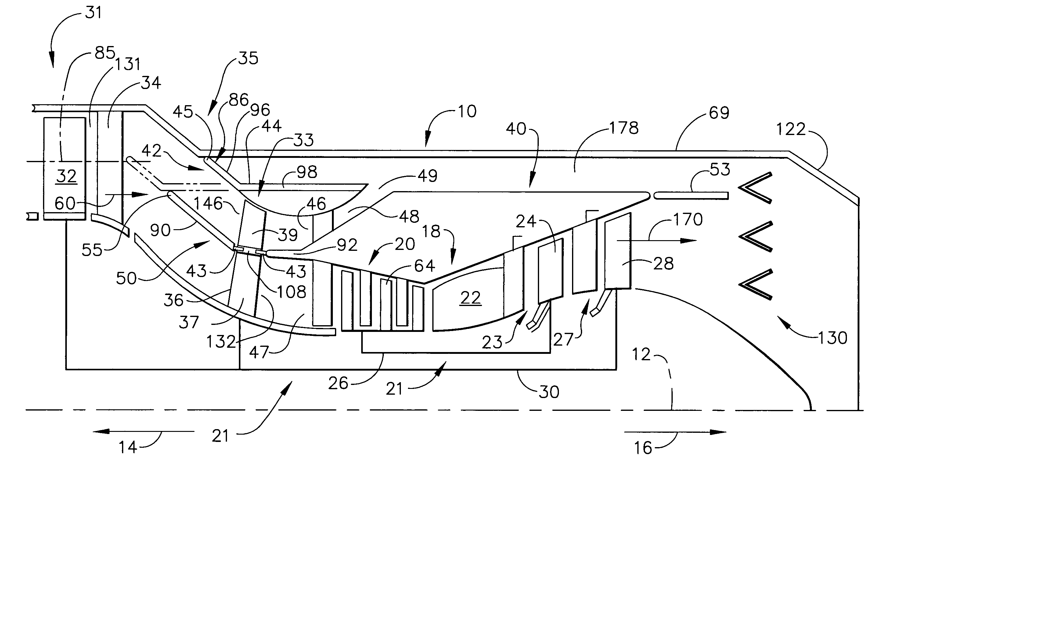
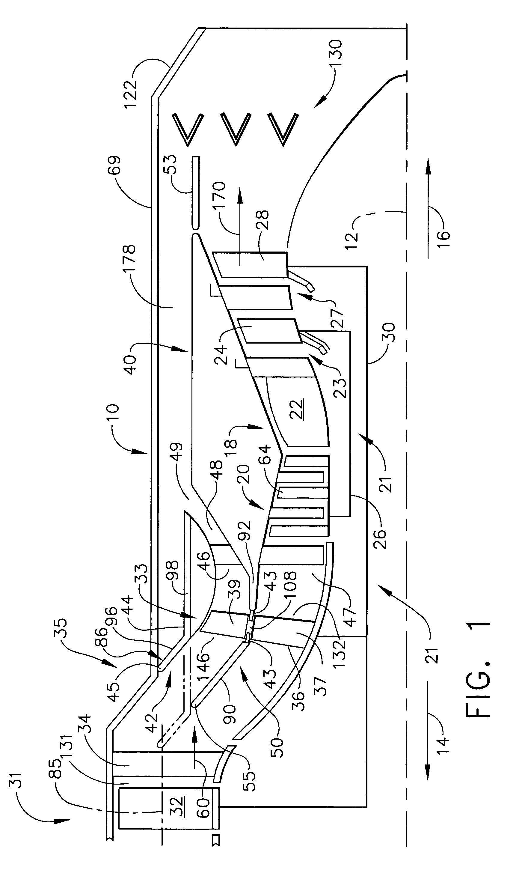
[0023]Illustrated in FIG. 1 is a bypass turbofan engine 10 having a generally axially extending axis or centerline 12 generally extending in a forward direction 14 and an aft direction 16. The bypass turbofan engine 10 includes a core engine 18 (also called a gas generator) which includes a high pressure compressor 20, a combustor 22, and a high pressure turbine (HPT) 23 having a row of high pressure turbine blades 24, all arranged in a serial, axial flow relationship. High pressure compressor blades 64 of the high pressure compressor 20 are fixedly connected in driving engagement to the high pressure turbine blades 24 by a larger-diameter annular core engine shaft 26 which is disposed coaxially about the centerline 12 of the engine 10 forming a high pressure spool 21.

[0024]A combustor 22 in the core engine 18 mixes pressurized air from the high pressure compressor 20 with fuel and ignites the resulting fuel and air mixture to produce combustion gases. Some work is extracted from th...


PUM


Abstract

A multiple bypass turbofan engine includes axially spaced-apart first and second stage fans of the engine fan connected in driving engagement to a low pressure shaft. A fan bypass duct circumscribes the second stage fan. A first bypass inlet to the fan bypass duct is disposed axially between the first and second stage fans and a second bypass inlet is axially disposed between the second stage fan and an annular core engine inlet. A fan shroud divides the second stage fan blades into radially inner and outer fan hub and tip sections, respectively. The tip sections are radially disposed in a fan tip duct. An axially translatable deflector is positioned to close the fan tip duct when it opens the first bypass inlet and open the fan tip duct when it closes the first bypass inlet.

Description

BACKGROUND OF THE INVENTION[0001]1. Field of the Invention[0002]The invention relates to aircraft gas turbine engines and, particularly, for such engines having multiple fan bypasses.[0003]2. Description of Related Art[0004]A conventional gas turbine engine includes a core engine having in serial, axial flow relationship, a high pressure compressor to compress the airflow entering the core engine, a combustor in which a mixture of fuel and the compressed air is burned to generate a propulsive gas flow, and a high pressure turbine which is rotated by the propulsive gas flow and which is connected by a radially inner relatively large diameter shaft to drive the high pressure compressor. A typical bypass turbofan engine adds a low pressure turbine aft of the high pressure turbine and adds a forward fan forward of the high pressure compressor.[0005]A typical variable bypass ratio design as, disclosed in U.S. Pat. No. 4,068,471, includes one or more forward rows of fan rotor blades in th...

Claims


Application Information

Patent Timeline
Patent Type & Authority Patents(United States)
IPC IPC(8): F01D17/14F01D17/00F01D17/10F02K3/06F02K3/075F02K3/00F02K3/02
CPCF01D17/105F02K3/075F02K3/06F01D17/141
Inventor CHRISTOPHERSON, CHARLES KAMMER
Owner GENERAL ELECTRIC CO
Why Eureka
Try Eureka