Substrate cleaning apparatus

Inactive Publication Date: 2005-06-07
DAINIPPON SCREEN MTG CO LTD
View PDF28 Cites 28 Cited by
  • Summary
  • Abstract
  • Description
  • Claims
  • Application Information

AI Technical Summary

Benefits of technology

[0023]Still another objective of the present invention is to im

Problems solved by technology

Consequently, fine particles such as dusts and slurries tend to remain on the surface of the substrate W,

Method used


Image

  • Substrate cleaning apparatus
  • Substrate cleaning apparatus
  • Substrate cleaning apparatus

Examples


Embodiment Construction

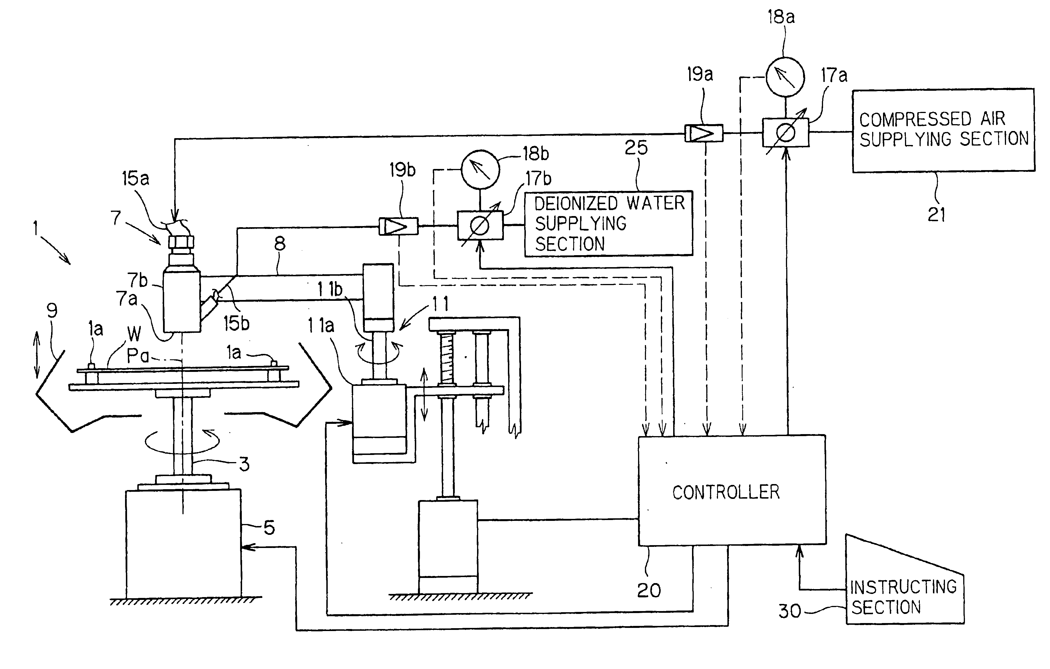
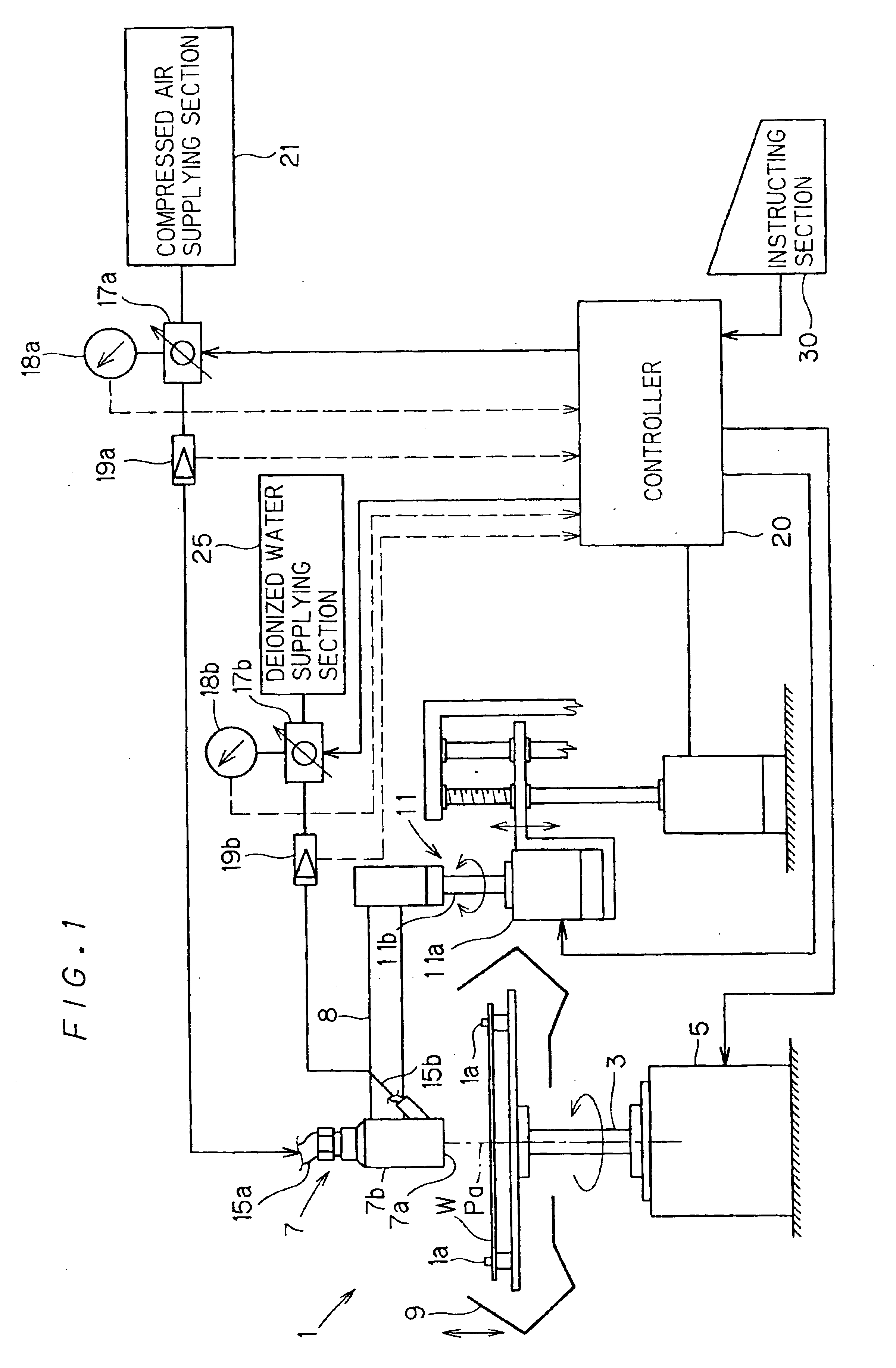
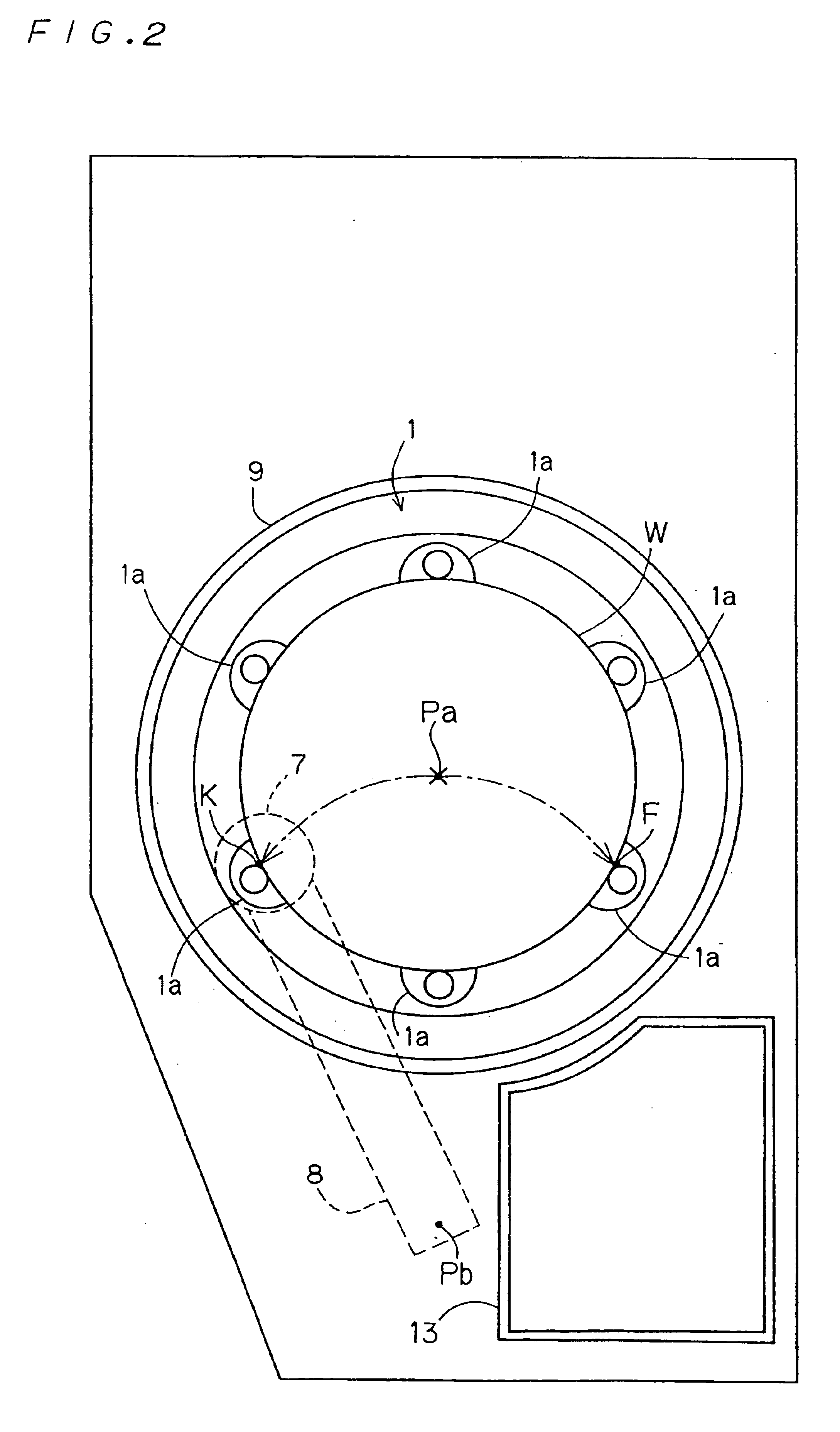
[0032]FIG. 1 is a block diagram that shows a schematic construction of a substrate cleaning apparatus in accordance with a first preferred embodiment of the present invention, and FIG. 2 is a plan view thereof.

[0033]The apparatus comprises a disc-shaped spin chuck 1, and six support pins 1a are attached to the spin chuck 1 in a protruding manner. As illustrated in FIG. 1, the spin chuck 1 is allowed to rotate by an electric motor 5 through a rotary shaft 3 connected to the bottom surface thereof. A substrate W, which is supported by the support pins 1a contacting the circumferential edge thereof, is rotated within a horizontal plane around the rotation center Pa by this rotative driving operation. A scattering preventive cup 9 for preventing the scattering of a cleaning liquid M discharged from a double fluids cleaning nozzle 7 is placed on the periphery of the spin chuck 1. The cleaning liquid may be remover liquid for removing residual pollution from the surface of the substrate. ...


PUM


Abstract

The substrate processing apparatus is provided with a gas-liquid mixing nozzle for generating a gas-liquid mixture by mixing a liquid and a pressurized gas, to discharge the gas-liquid mixture to a substrate at high speeds. The mixture process is conducted in an open space out of the nozzle, and change in the supply pressure of the gas does not affect the supply of the liquid. The reaction products which having been generated on the substrate in etching process is removed at high speeds with the flow of the gas-liquid mixture, whereby the quality of the process is improved.

Description

[0001]This application is a divisional of application Ser. No. 09 / 987,270, filed Nov. 14, 2001, now U.S. Pat. No. 6,705,331.BACKGROUND OF THE INVENTION[0002]1. Field of the Invention[0003]The present invention relates to an apparatus for applying cleaning process to various substrates such as a semiconductor wafer, a glass substrate for a liquid crystal display, a PDP (Plasma Display Panel) substrate or a glass substrate and a ceramic substrate for magnetic discs.[0004]2. Description of the Background Art[0005]A process of manufacturing semiconductor devices includes a step of forming a thin film on a semiconductor wafer (hereinafter referred to as “substrate”) and then selectively removing the thin film through etching process, which is repeated to obtain fine patterns on the substrate. Respective surfaces of the substrate, in particular, the major surface of the substrate on which thin films are to be formed, should be clean to precisely obtain the fine patterns on the substrate. ...

Claims


Application Information

Patent Timeline
IPC IPC(8): B08B3/02B08B1/04H01L21/00
CPCB08B1/04B08B3/02H01L21/67046Y10S134/902B08B2203/0288
Inventor SATO, MASANOBUHIRAE, SADAOYASUDA, SHUICHIMORINISHI, KENYA
Owner DAINIPPON SCREEN MTG CO LTD
Why Eureka
Try Eureka