Transaxle apparatus and four-wheel driving working vehicle using the apparatus

a technology of working vehicle and transaxle, which is applied in the direction of fluid couplings, couplings, transportation and packaging, etc., can solve the problems of difficult bailing, power take-off shaft for driving the working device cannot be used as a front wheel drive shaft, and the two-wheel drive vehicle which drives only the rear wheels is inferior in its gradablility, so as to improve the workability of assembling the transaxle apparatus

Inactive Publication Date: 2005-06-07
KANZAKI KOKYUKOKI MFG
View PDF9 Cites 30 Cited by
  • Summary
  • Abstract
  • Description
  • Claims
  • Application Information

AI Technical Summary

Benefits of technology

[0018]Therefore, according to the present invention, the housing of the transaxle apparatus which arranges the power transmitting means therein is constituted by two housing components separably joined to each other through the first level surface, thereby improving the workability in assembling the transaxle apparatus.
[0019]Furthermore, if the articulate vehicle enabled to drive with four wheels has a working device attached onto the frame other than the frame on which the prime mover is mounted, it also becomes necessary to provide other means for transmitting power from the prime mover to the working device. A second object of the present invention is to provide an articulate vehicle in which a power train for four-wheel driving and a power train for driving the working device are compactly interposed between the front and rear transaxle apparatuses while they are prevented from interfering with each other.

Problems solved by technology

However, the two-wheel drive vehicle which drives only rear wheels is inferior in its gradablility when working on a slope and roadability when running on a bad road.
There arise some problems such that the vehicle, when being in mud etc., is hard to bail out.
Therefore, the power take-off shaft for driving the working device cannot be used as a front wheel drive shaft as it is.
For this reason, existence of the coupling part between the rear frame and the front frame complicates the configuration of the power transmitting system of these two trains.

Method used


Image

  • Transaxle apparatus and four-wheel driving working vehicle using the apparatus
  • Transaxle apparatus and four-wheel driving working vehicle using the apparatus
  • Transaxle apparatus and four-wheel driving working vehicle using the apparatus

Examples


Embodiment Construction

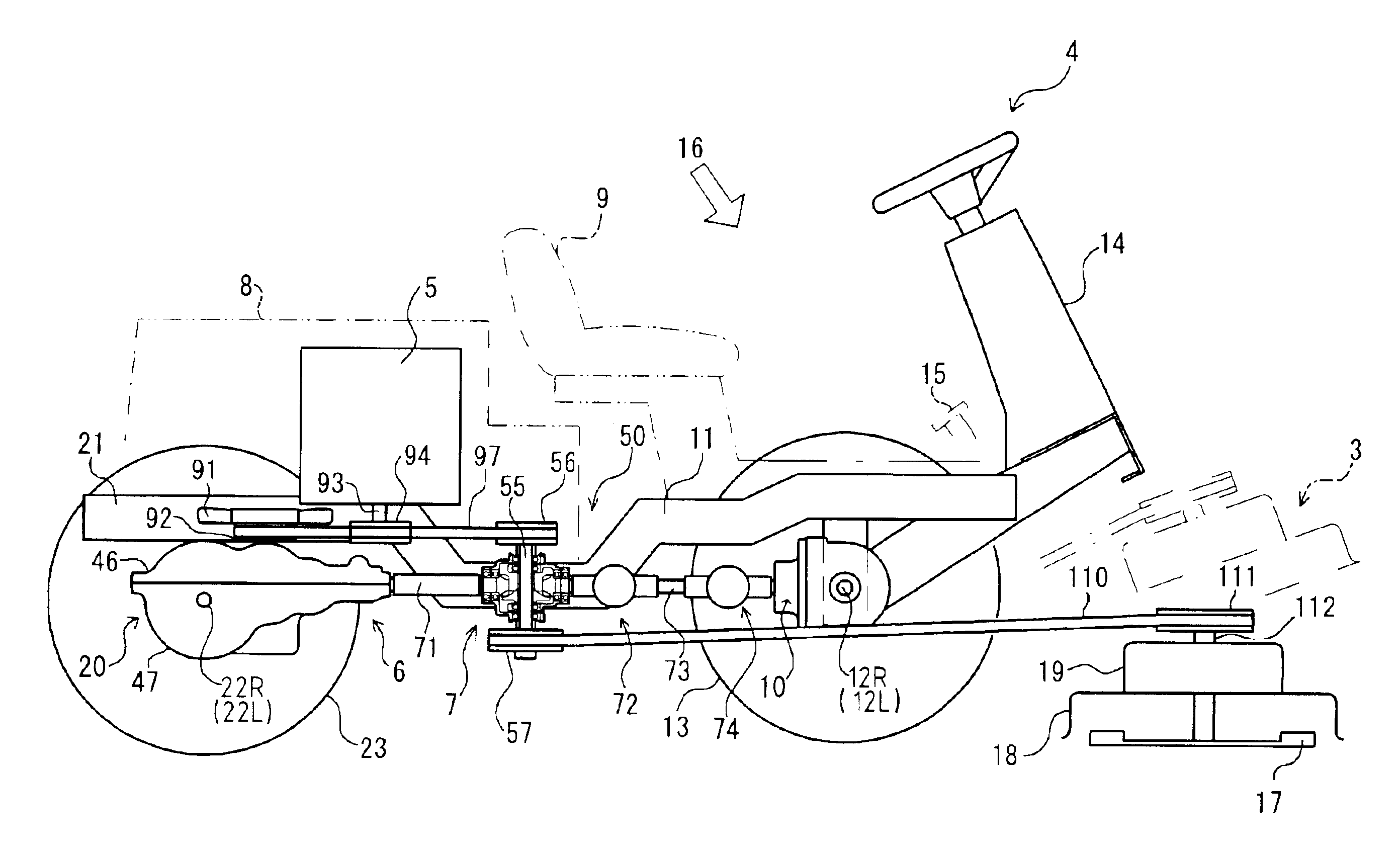
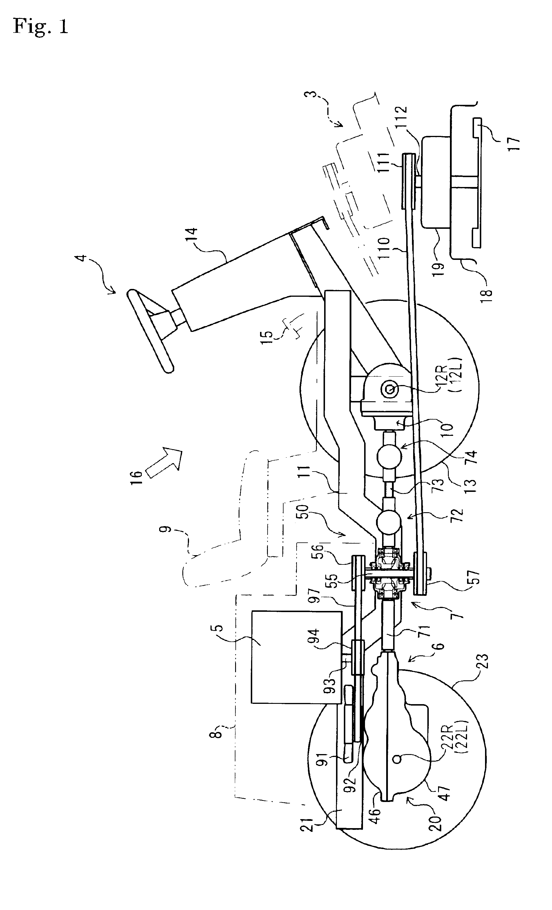
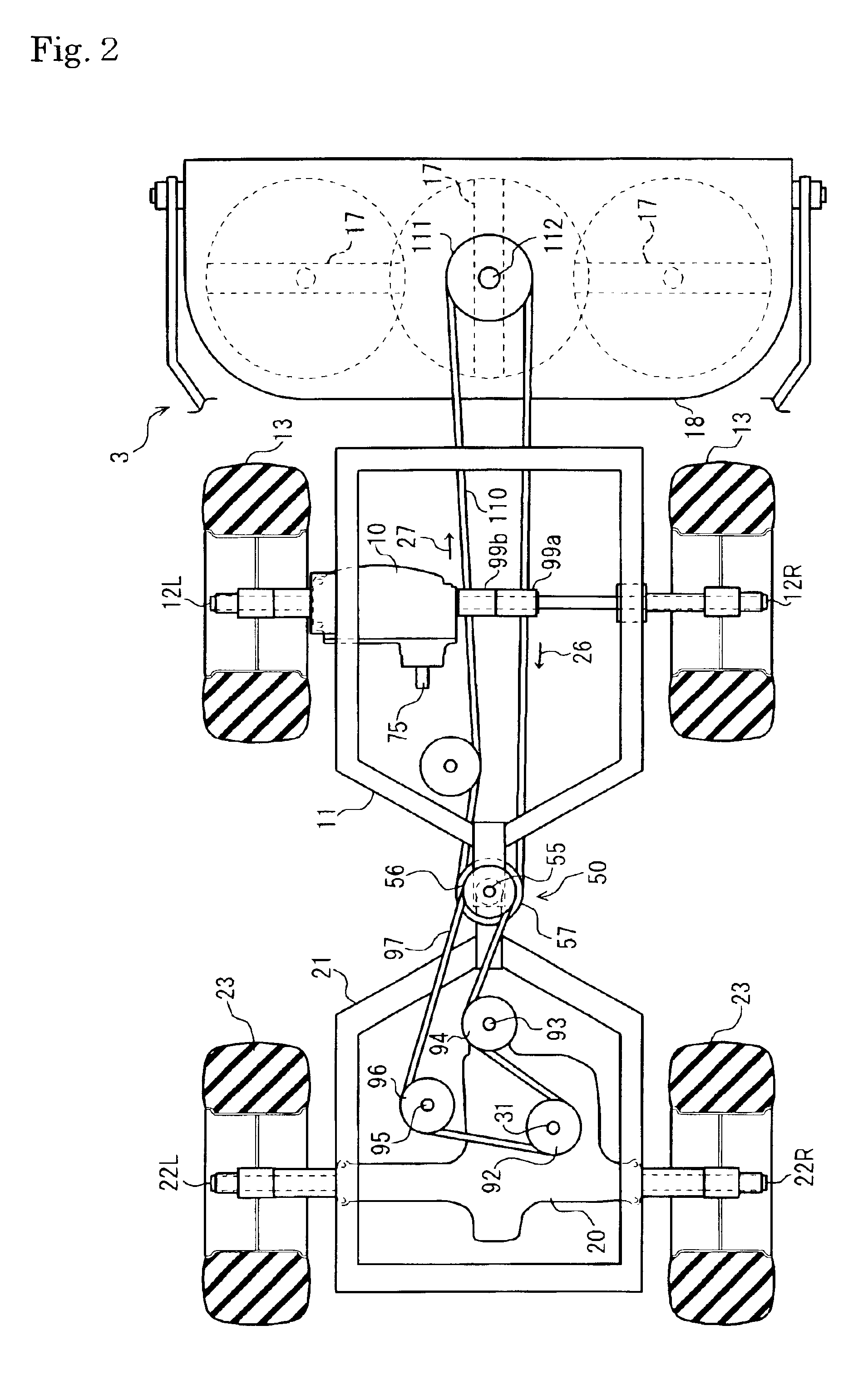
[0031]A working vehicle shown in FIG. 1 is a lawn mower provided at a front portion thereof with a mower device 3 serving as a working device. A first transaxle apparatus 20 is arranged on a rear frame 21 serving as a first frame. Left and right rear wheel axles 22L and 22R are extended laterally from the first transaxle apparatus 20 and fixedly provided thereon with respective rear wheels 23. On the other hand, a second transaxle apparatus 10 is arranged on a front frame 11 serving as a second frame. Left and right front wheel axles 12L and 12R are extended laterally from the second transaxle apparatus 10 and fixedly provided thereon with respective front wheels 13.

[0032]A rear end portion of the front frame 11 and a front end portion of the rear frame 21 are mutually connected horizontally rotatably at a pivotal coupling part 50 so as to enable the front frame 11 to turn laterally relative to the rear frame 21, thereby making the vehicle into a so-called articulate vehicle.

[0033]O...


PUM


Abstract

An articulate vehicle has first and second frames, which are coupled to each other at proximal ends thereof with respect to the vehicle through a coupling part so as to be relatively rotatable around a vertical axis according to steering operation. The first and second frames are distributed at front and rear portions of the vehicle. The first frame supports a first transaxle apparatus having first axles, and the second frame supports a second transaxle apparatus having a pair of second axles. A gearbox is disposed near the coupling part and provided with a pair of mutually drivingly connected horizontal shafts which are variable in relative angles thereof around the vertical axis according to steering operation. One of the horizontal shafts is drivingly connected to a power take-off shaft for extracting output power of a speed-changing arrangement in the first transaxle apparatus. The other of the horizontal shafts is drivingly connected to an input shaft of the second transaxle apparatus. The vehicle is provided with a rotor having a rotary axis disposed on the vertical axis so as to output power from a prime mover to a working device.

Description

BACKGROUND OF THE INVENTION[0001]1. Field of the Invention[0002]The invention relates to a structure of an articulate vehicle, such as a riding lawn mower, comprising two mutually pivotally connected front and rear frames equipped with respective transaxle apparatuses supporting axles with wheels mounted thereon. More particularly, it relates to a structure for transmitting driving force to the transaxle apparatuses of both the frames from a prime mover, a structure for transmitting driving force from the prime mover to a working device attached to one of the frames, and a structure with a coupling part of the front and rear frames.[0003]2. Related Art[0004]Conventionally, there is a well-known articulate riding lawn mower having mutually pivotally connected first and second frames so as to enable the first frame to turn relative to the second frame. The first frame is disposed at one of front and rear portions of the vehicle and equipped with a prime mover and a transaxle apparatus...

Claims


Application Information

Patent Timeline
Patent Type & Authority Patents(United States)
IPC IPC(8): B60K17/28B60K17/10B60K17/00A01D69/03B62D12/00
CPCA01D69/03B62D12/00B60Y2200/223B60K17/105
Inventor OHASHI, RYOTA
Owner KANZAKI KOKYUKOKI MFG
Why Eureka
Try Eureka