Exhaust pipe decoupler for vehicles

a technology for exhaust pipes and couplers, applied in the direction of mechanical equipment, machines/engines, adjustable joints, etc., can solve the problems of low control capability, low durability and noise, and the possibility of excessive displacement in any direction, so as to improve productivity and reliability, improve the effect of deformation and displacement durability

Inactive Publication Date: 2005-06-07
SJM
View PDF27 Cites 35 Cited by
  • Summary
  • Abstract
  • Description
  • Claims
  • Application Information

AI Technical Summary

Benefits of technology

[0024]In case that heavy outer forces, i.e., tension and compression displacements are applied to the bellows 10, a ring damper 40 is mounted outward the retainer 30 fixed between the outer braid member and the bellows 10 in order to control movement of the bellows 10 within the elastic range, so that motion of the excessive tension fo...

Problems solved by technology

There is a possibility of excessive displacement in any direction, such as tension compression, bending or deflection.
The interlock member in spiral may cause problems regarding durability and noise, dependent on the closing method of the opposite ends.
However, excessive displacement and heavy stress on the bellows itself result in low controlling capability.
Since the c...

Method used


Image

  • Exhaust pipe decoupler for vehicles
  • Exhaust pipe decoupler for vehicles
  • Exhaust pipe decoupler for vehicles

Examples


Embodiment Construction

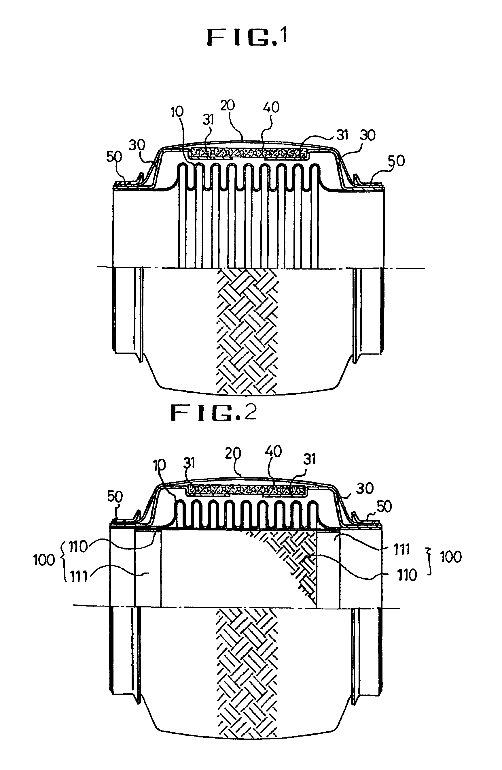
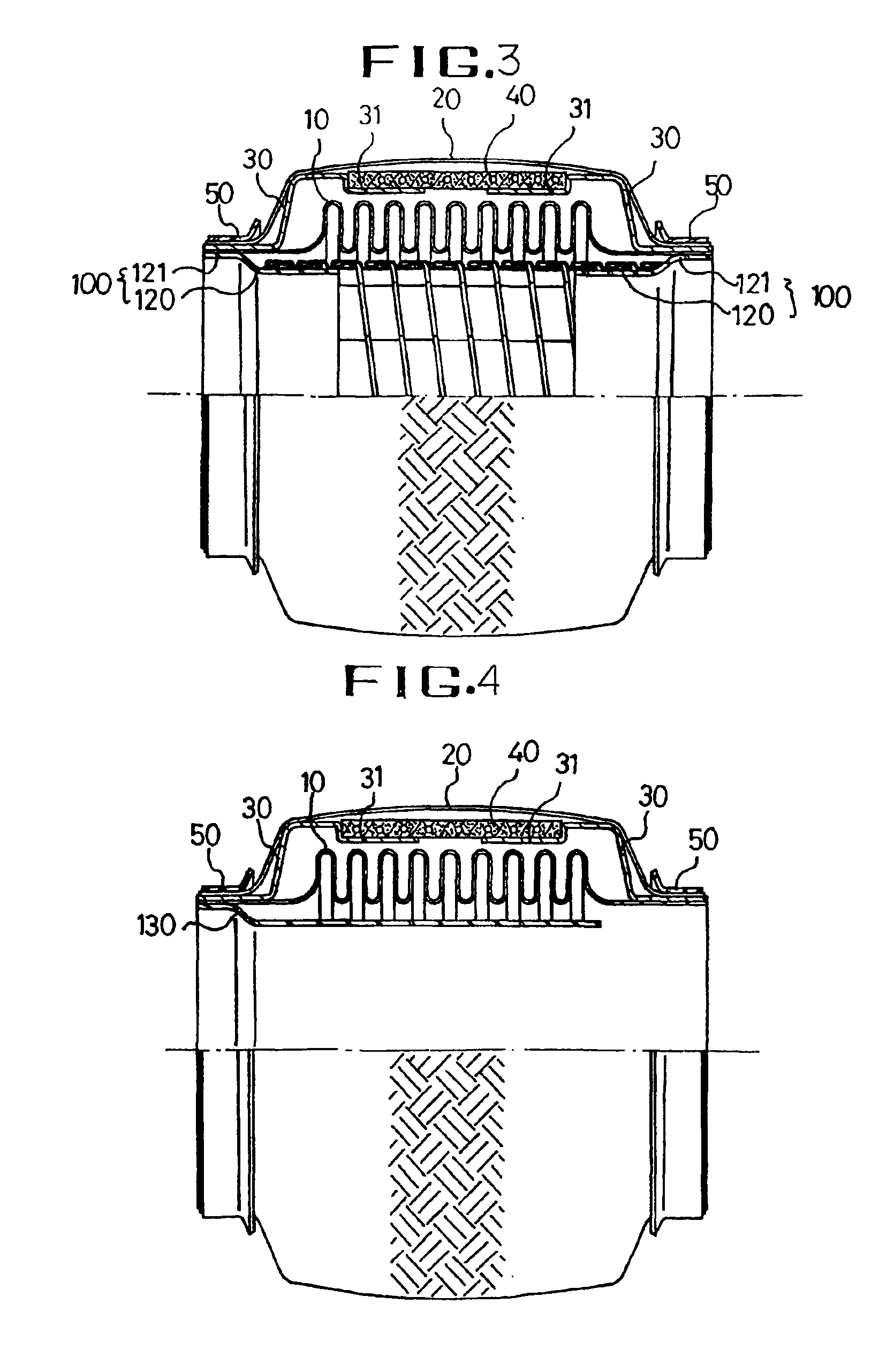
[0032]The presently preferred embodiments of the invention will be best understood by reference to the drawings in which: FIG. 1 is a sectional view of the exhaust pipe coupler of the present invention; FIG. 2 is a sectional view with the inner braid member of the present invention; FIG. 3 is a sectional view with the interlock member of the present invention; FIG. 4 is a sectional view with the sleeve member for guiding the exhaust gas; FIG. 5 is a sectional view of the inner ring damper; FIG. 6 is a sectional view with the a protecting cover at each end of the outer braid member; FIG. 7 is a sectional view in which the ring damper fills the interval in the middle of retainers fixed at opposite ends of the bellows; and FIG. 8 is a sectional view showing the ring damper on the retainers to form slant of the ends of the ring damper and the support on which the ring dampers are seated.

[0033]Referring to FIG. 1, a bellows 10 cylindrically formed in a repeatedly corrugated shape is made...


PUM


Abstract

An exhaust pipe decoupler for vehicles including a bellows (10), an outer braid member (20) spaced from the bellows and braided with a predetermined angle, a retainer (30) having a support (31) inwardly curved at both ends thereof for engaging to a ring damper (40), the retainer being affixed to the ends of the bellows (10) and installed between the outer surface of the bellows (10) and the outer braid member (20) to prevent direct contact thereof, the ring damper (40) located outward the support (31) formed in the retainer (30), a fixing cap (50) coupled to the outer diameter of the outer braid member (20) in order that the outer braid member (20) and the retainer (30) are located outward the bellows (10), wherein the outer braid member (20) absorbs tension in excessive outer forces, i.e., displacement of tension and compression, and the ring damper (40) controls the displacement of compression and shear displacement by the ring damper (40), thereby controlling the bellows within the elastic range.

Description

TECHNICAL FIELD[0001]The present invention relates to an exhaust pipe coupler for vehicles, and more particularly, an exhaust pipe coupler wherein a ring-shaped damper affixed by a retainer is inserted into the interior of the outer braid member in an exhaust system for vehicles, for reducing excessive outer forces and displacement applied to the bellows to improve durability of the bellows.BACKGROUND ART[0002]It is well known that vehicle engines are coupled to the exhaust pipe employing a muffler for exhausting the exhaust gas from the vehicle and the coupler acts to absorb and buffer the vibration displacement, impact load or heat deformation.[0003]The coupler on this location should be mounted to absorb engine and road vibrations and displacement. There is a possibility of excessive displacement in any direction, such as tension compression, bending or deflection.[0004]In order to improve absorbing capability of the vibration displacement and maintain airtightness of the coupler...

Claims


Application Information

Patent Timeline
IPC IPC(8): F01N7/18F16L27/11F16L27/00F01N13/08F01N13/18
CPCF01N13/1811F16L27/11F01N13/1816F01N13/08
Inventor KANG, CHOON KI
Owner SJM
Why Eureka
Try Eureka