Piezoelectric resonator, piezoelectric resonator component and method of making the same

a piezoelectric resonator and component technology, applied in piezoelectric/electrostrictive/magnetostrictive devices, piezoelectric/electrostrictive/magnetostriction machines, piezoelectric/electrostrictive devices, etc., can solve problems such as deterioration of characteristics, variation or reduction of joint adhesive strength, and difficulty in stabilizing and fixing substrates. stably supported

Inactive Publication Date: 2005-06-07
TDK CORPARATION
View PDF19 Cites 12 Cited by
  • Summary
  • Abstract
  • Description
  • Claims
  • Application Information

AI Technical Summary

Benefits of technology

[0015]An object of the present invention is to provide a piezoelectric resonator which can be supported stably with minimized suppression of vibration energy and to provide a component having the same.

Problems solved by technology

In a small-sized component, in particular, the whole piezoelectric substrate vibrates, making it difficult to support and fix the substrate stably.
Variation or reduction in joint adhesive strength is liable to lead to deterioration of characteristics due to vibration energy suppression, deterioration of resonance characteristics due to insufficient control of spurious vibrations, and oscillation defects such as instable skipping of necessary oscillation.
In such a structure wherein a piezoelectric transducer is fixed to one side of a substrate via a connecting conductor, differences in linear expansion coefficient among the connecting conductor, the substrate and the piezoelectric transducer tend to produce thermal stress, which can develop cracks in the connecting conductors.
This results in reduced reliability of interconnectivity of the components.
However, because the proposed connecting conductor has a resin ball as a nucleus, it is likely that the adhesive area between the connecting conductor and the substrate or the piezoelectric transducer varies and the adhesive strength therebetween tend to be reduced.
There is another problem that some components in the resin ball tend to seep and the adhesive strength therebetween tend to be reduced.
The above-described prior arts, however, do not teach techniques for relaxing the thermal stress arising from the difference of linear expansion coefficient because the materials proposed for forming the nucleus show linear expansion coefficients largely different from those of the piezoelectric element or the substrate.

Method used


Image

  • Piezoelectric resonator, piezoelectric resonator component and method of making the same
  • Piezoelectric resonator, piezoelectric resonator component and method of making the same
  • Piezoelectric resonator, piezoelectric resonator component and method of making the same

Examples


example 1

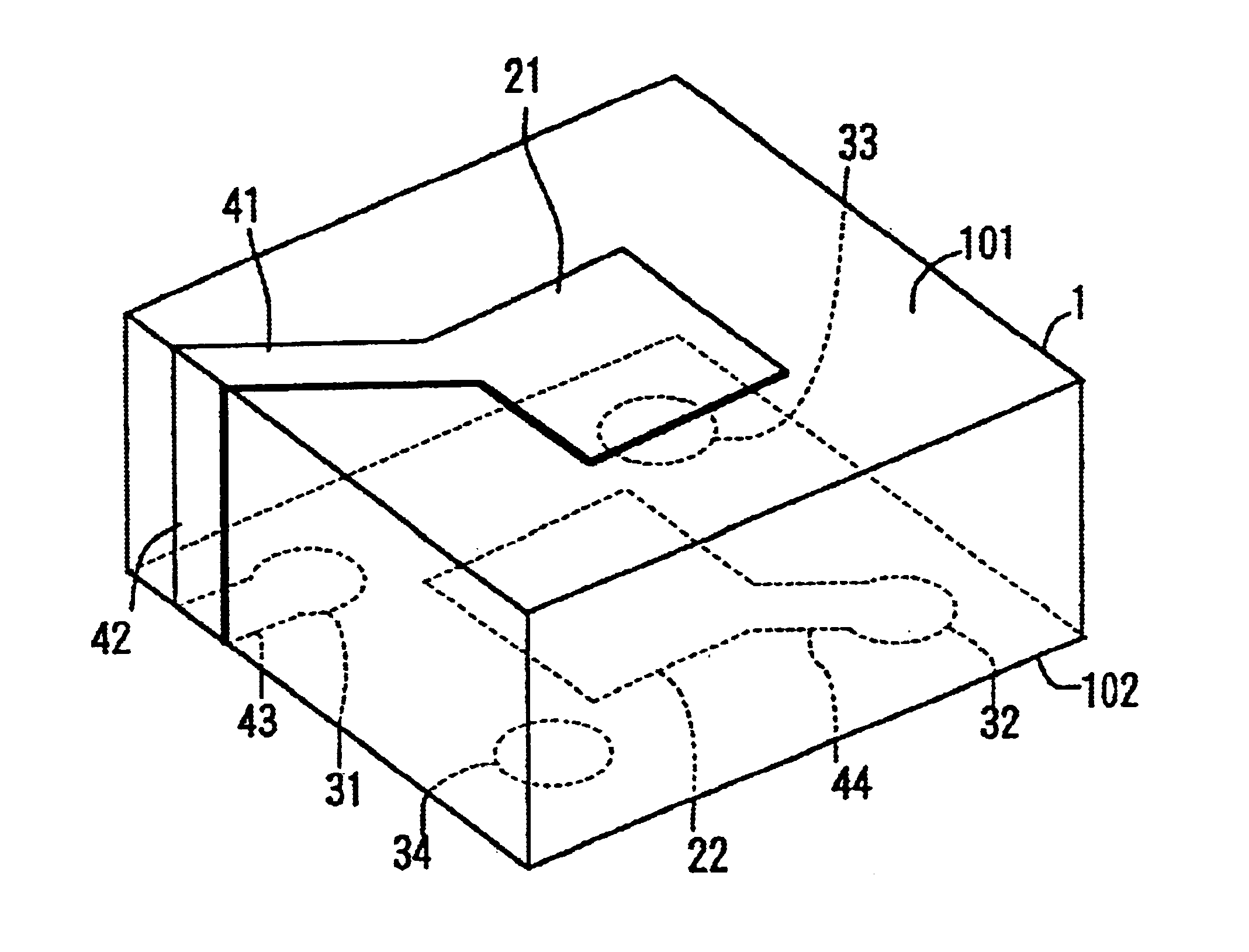
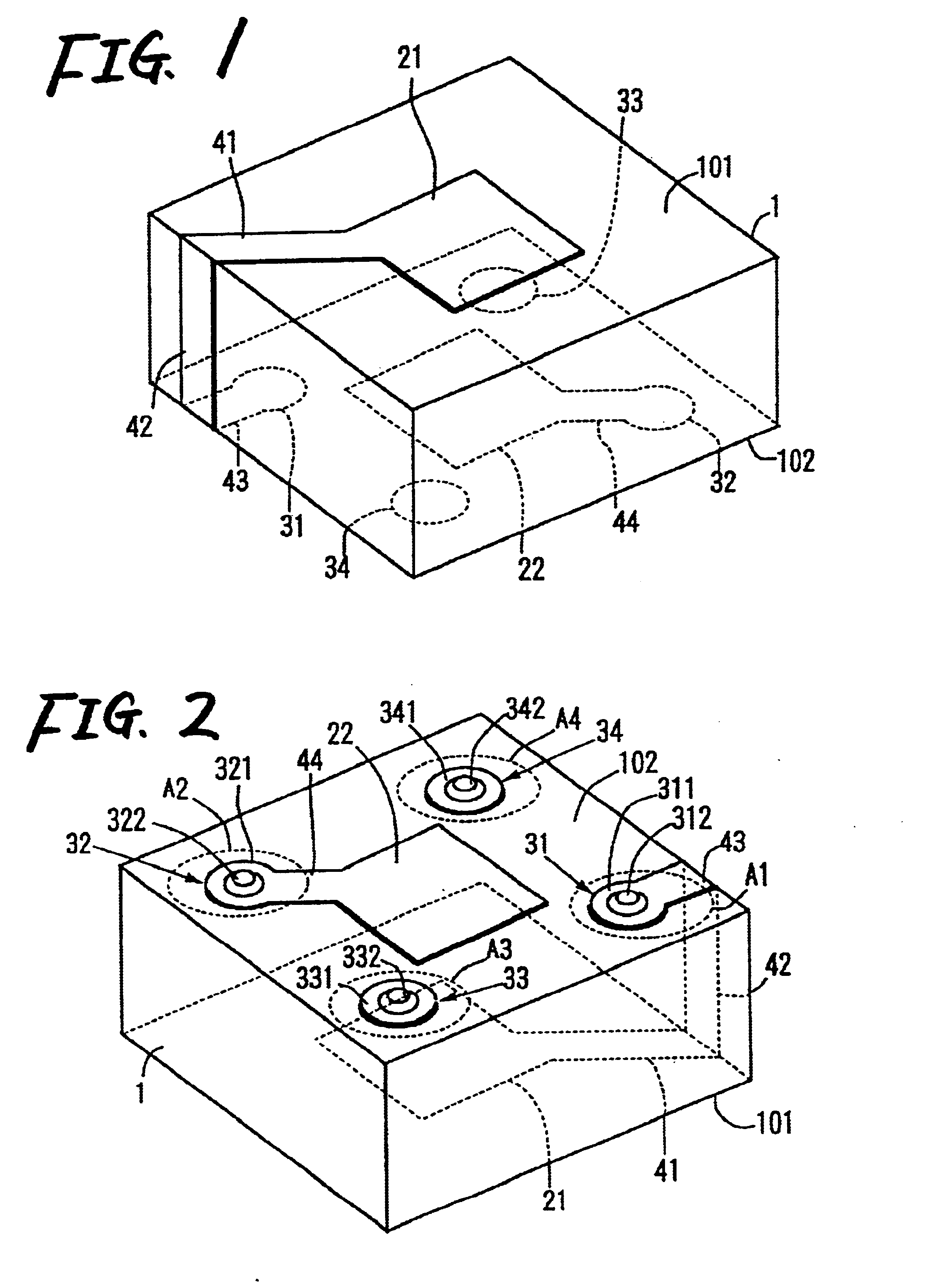
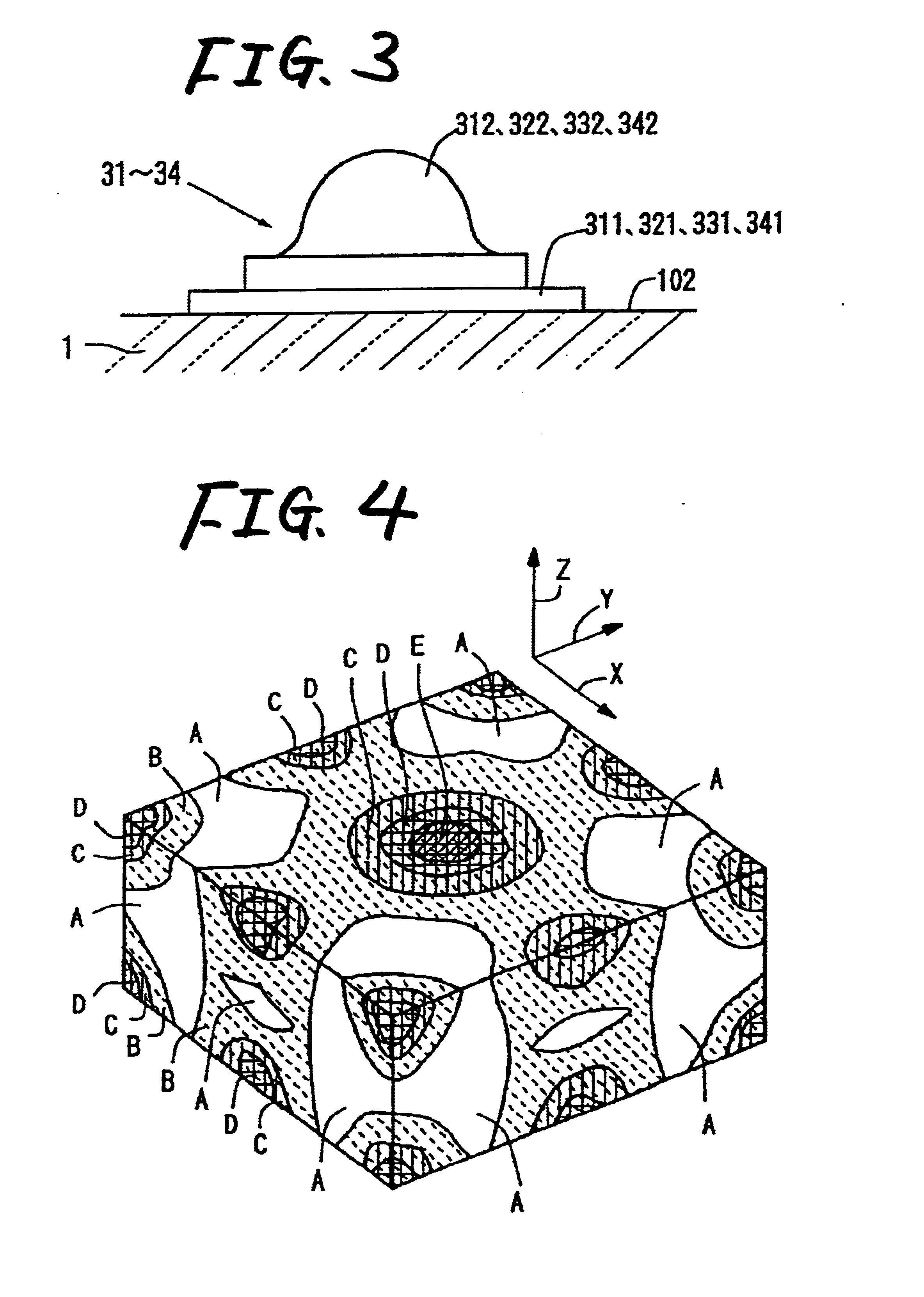
[0121]Ten samples of the piezoelectric resonator component having the structure shown in FIGS. 1 to 3 were prepared and subjected to a thermal shock test. In the thermal shock test, the samples were maintained at −40° C. for 30 minutes and then at 85° C. for 30 minutes to make one heat cycle, which was repeated 100 times. The materials of the constituent members, their linear expansion coefficient, and the results of the thermal shock test are shown in Table 1.

example 2

[0122]Ten samples of the piezoelectric resonator component having the structure shown in FIGS. 1 to 3 were prepared and subjected to a thermal shock test. In the thermal shock test, the samples were maintained at −40° C. for 30 minutes and then at 85° C. for 30 minutes to make one heat cycle, which was repeated 100 times. The materials of the constituent members, their linear expansion coefficient, and the results of the thermal shock test are shown in Table 1. The difference from Example 1 is that “US” is used in Example 2 as a ceramics substrate, while “SLBT” is used in Example 1. Here, “US” represents SrTiO3—CaTiO3 ceramics, and “SLBT” represents a bismuth compounds with layer structure.


PUM


Abstract

A first vibrating electrode is provided on a first side of a piezoelectric substrate perpendicular to the thickness direction. A second vibrating electrode is provided on a second side opposite to the first side to face the first vibrating electrode. A first pad and a second pad are respectively formed on a side of the piezoelectric substrate perpendicular to the thickness direction in area having a small vibration displacement. The first pad and the second pad are electrically connected to the first vibrating electrode and the second vibrating electrode.

Description

BACKGROUND OF THE INVENTION[0001]1. Field of the Invention[0002]The present invention relates to a piezoelectric resonator, a piezoelectric resonator component, and a method of making the same.[0003]2. Description of the Related Art[0004]Conventionally, piezoelectric resonator components making use of a piezoelectric transducer as a resonator for obtaining oscillation frequencies are known. An example of a piezoelectric transducer includes a piezoelectric substrate with a pair of electrodes on one side and the opposite side thereof. The piezoelectric resonator component has the piezoelectric transducer fixed to a capacity element providing two load capacities which constitute an oscillation circuit, with one side of the former perpendicular to the thickness direction facing one side of the latter perpendicular to the thickness direction. The piezoelectric resonator component also has an input electrode, an output electrode, and a grounding electrode electrically and mechanically con...

Claims


Application Information

Patent Timeline
Patent Type & Authority Patents(United States)
IPC IPC(8): H03H9/00H03H9/17H03H9/02H03H9/10
CPCH03H9/02094H03H9/02133H03H9/177H03H9/0514H03H9/1014H03H9/0504
Inventor SUZUKI, TOSHIYUKIMIKI, NOBUYUKI
Owner TDK CORPARATION
Why Eureka
Try Eureka