Cursor control console with rotary knob and method of use

a cursor control and rotary knob technology, applied in the field of input devices of vehicles, can solve the problems of difficult use, difficult to precisely control ccds, and particularly difficult use of ccds in aircraft, and achieve the effect of enhancing the human interface of the aircraft flight deck and facilitating the entry of alpha and numeric data

Inactive Publication Date: 2005-06-07
HONEYWELL INC
View PDF37 Cites 17 Cited by
  • Summary
  • Abstract
  • Description
  • Claims
  • Application Information

AI Technical Summary

Benefits of technology

[0009]The invention discloses a control console having both a cursor control device(CCD) and a rotary knob to facilitate entering alpha and numeric data. The rotary knob is located within finger reach of the cursor control device such that an operator can manipulate either the CCD or the knob with movement of only the operator's fingers, hand, and / or wrist. An operator manipulates the cursor control device to select a desired parameter then spins or rotates the rotary knob to display the desired alpha or numeric value. A button is provided to select or enter the data. The method of using the invention significantly enhances the human interface of an aircraft flight deck.
[0011]The first advantage is accessibility of the knob. Since the pilot or operator's hand is already on the console, it is convenient to have the knob there also.
[0012]Another advantage is less distraction of the pilot. Prior systems required the pilot to visually locate dedicated control knobs then manipulate them as desired. The pilot is distracted while locating and manipulating these knobs. The invention locates the knob conveniently so that the pilot can easily locate the knob without visual assistance.
[0013]Yet another advantage is reduced cost. When used in cooperation with a GUI, a single rotary knob on the console replaces many dedicated control knobs.
[0014]Therefore, the objects of the invention are to simplify the operator interface, reduce pilot / operator distraction, reduce the number of dedicated control panels, and reduce costs.

Problems solved by technology

Most CCDs function well in fixed or stable environments, however, they are difficult to use in vehicles where turbulence makes a CCD difficult to precisely control.
CCDs are particularly difficult to use in an aircraft where space is limited and the environment can be extremely turbulent during bad weather.
The consoles and CCDs of the prior art are deficient in that it is difficult to enter alpha and numeric data using the CCD.
Entering alphanumeric data with a typical CCD is slow and cumbersome.

Method used


Image

  • Cursor control console with rotary knob and method of use
  • Cursor control console with rotary knob and method of use
  • Cursor control console with rotary knob and method of use

Examples


Embodiment Construction

[0020]This description describes the invention as embodied in an aircraft flight deck / cockpit, however the invention is useful in other environments such as land and water based vehicles.

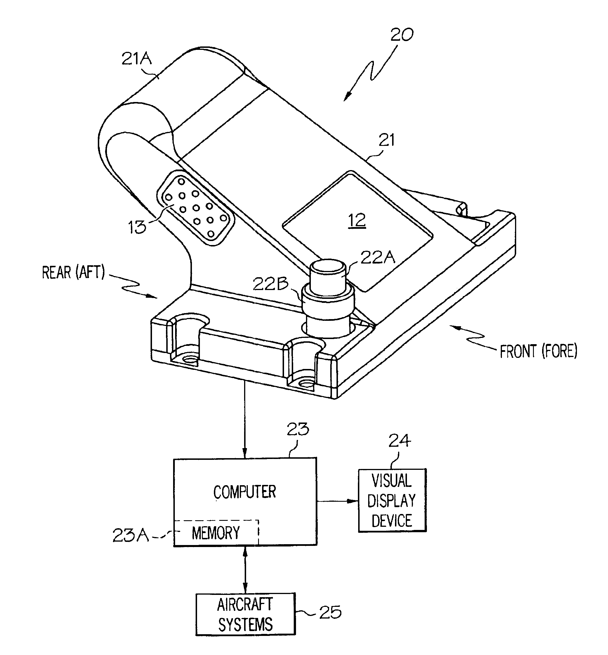
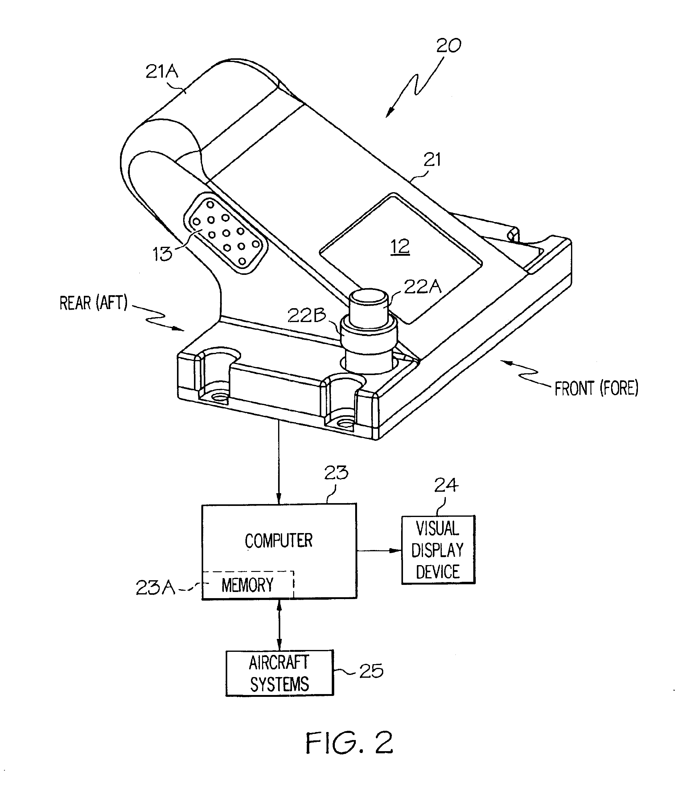
[0021]FIG. 2 illustrates the preferred embodiment of the invention. Control console 20 includes housing 21, wrist rest 21A, CCD 12, select buttons 13, and rotary knob 22. The ergonomics of console 20 are similar in some respects to the prior art. Console 20 is preferably located to the side of the pilot's seat within easy reach of the pilot. The pilot / operator positions his wrist or hand on the wrist rest 21A while manipulating CCD 12, rotary knob 22, and select button 13.

[0022]The key to the invention is rotary knob 22 which is within finger reach of CCD 12. The phrase “within finger reach” refers to the close proximity of the knob 22 and CCD 12. It means that rotary knob 22 and CCD 12 are sufficiently near to each other such that the pilot / operator can move to manipulate either device using moveme...


PUM


Abstract

A rotary knob is integrated into a cursor control console and facilitates entering of alpha and numeric data into an aircraft computer system. The console houses both a cursor control device and the rotary knob. The rotary knob is located within finger reach of the cursor control device such that an operator can manipulate either control with only movement of the users fingers, hand, and / or wrist. An operator manipulates the cursor control device to select a desired parameter. The operator then spins or rotates the knob to select the desired alpha or numeric value.

Description

BACKGROUND OF INVENTION[0001]The present invention relates generally to input devices and more specifically to vehicle based cursor control input devices.[0002]Computers are used in a wide range of applications from desktop personal computers for home and business applications to flight decks of jumbo jets for controlling the flight and operation of the aircraft. As computers have become more powerful, the need for improved human interfaces has become more important. Current computers typically use graphical user interfaces(GUIs) to improve and simplify the human interface. Graphical user interfaces use a cursor to select, activate, and manipulate various symbols, pages, icons, scroll bars, etc. on a display to accomplish desired results.[0003]The cursor is controlled using a cursor control device(CCD) such as a mouse, trackball, joystick, touchpad, or the like. These devices are typically accompanied by one or more buttons which the operator activates to select or enter various com...

Claims


Application Information

Patent Timeline
Patent Type & Authority Patents(United States)
IPC IPC(8): G06F3/033
CPCG06F3/03547G09G5/08G09G2380/12H01H2019/143
Inventor GLITHERO, JASON I.
Owner HONEYWELL INC
Why Eureka
Try Eureka