Erected mirror optical switch

a technology of optical switches and mirrors, applied in the field of microelectromechanical devices, to achieve the effect of high angular precision

Active Publication Date: 2005-06-07
NAT TECH & ENG SOLUTIONS OF SANDIA LLC
View PDF13 Cites 39 Cited by
  • Summary
  • Abstract
  • Description
  • Claims
  • Application Information

AI Technical Summary

Problems solved by technology

The existing optical switches which are tiltable within a limited angular range generally suffer from a need to have electrical power applied at all times in order to establish and maintain an optical connection; whereas other of the existing optical switches which continue to operate when the electrical power is removed are generally limited to only a pair of well-defined angular states.

Method used


Image

  • Erected mirror optical switch
  • Erected mirror optical switch
  • Erected mirror optical switch

Examples


Embodiment Construction

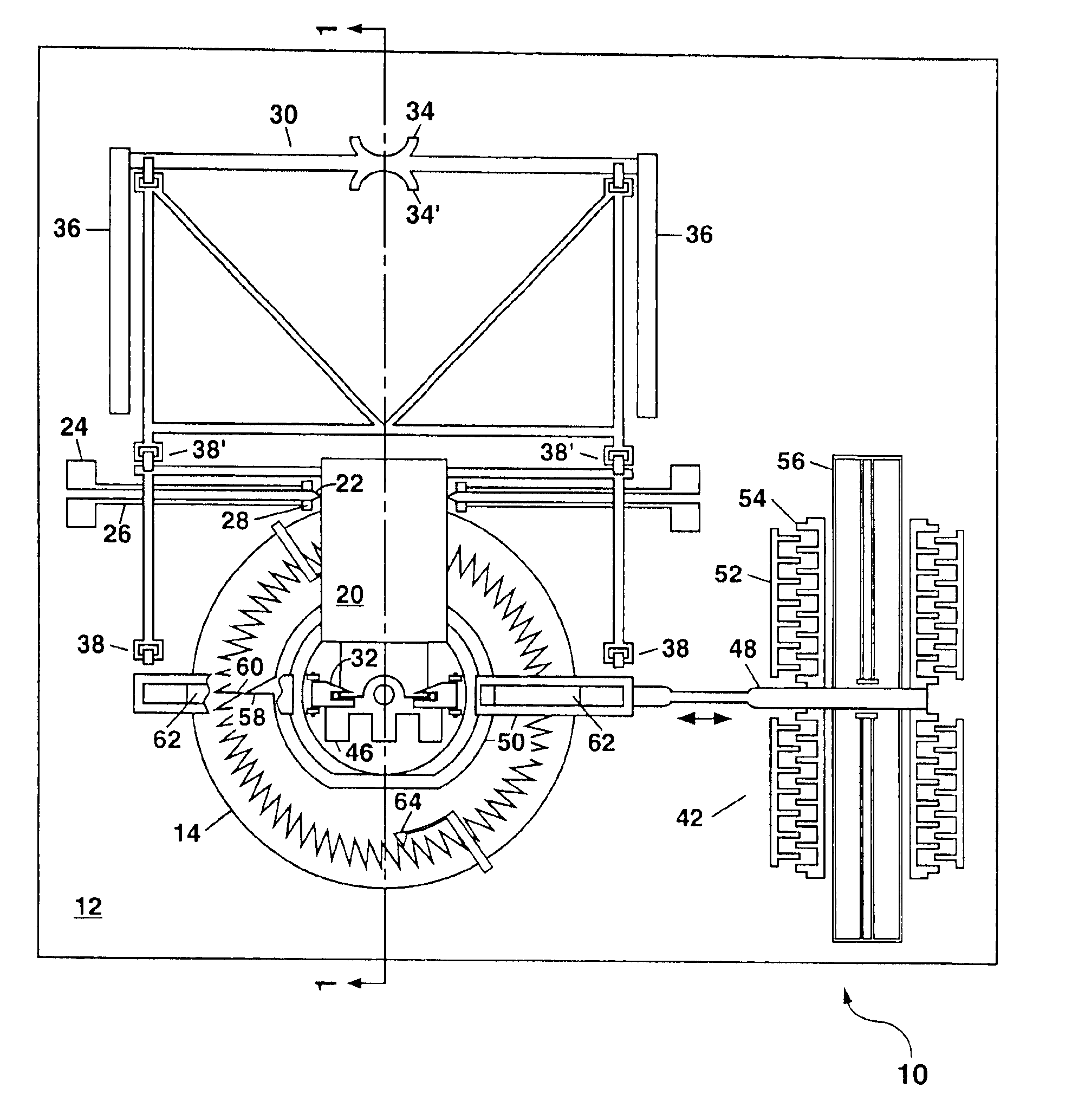
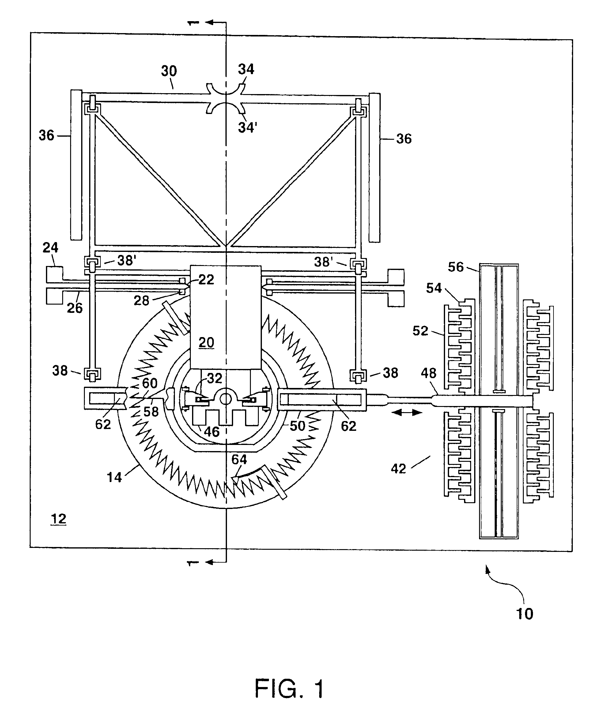
[0029]Referring to FIG. 1, there is shown a schematic plan view of an example of the microelectromechanical (MEM) optical switching apparatus 10 of the present invention in an as-fabricated state prior to the erection of a mirror 20 therein. The MEM optical switching apparatus 10 can be formed by surface micromachining on a substrate 12 which generally comprises silicon (e.g. a monocrystalline silicon substrate, or a silicon-on-insulator substrate).

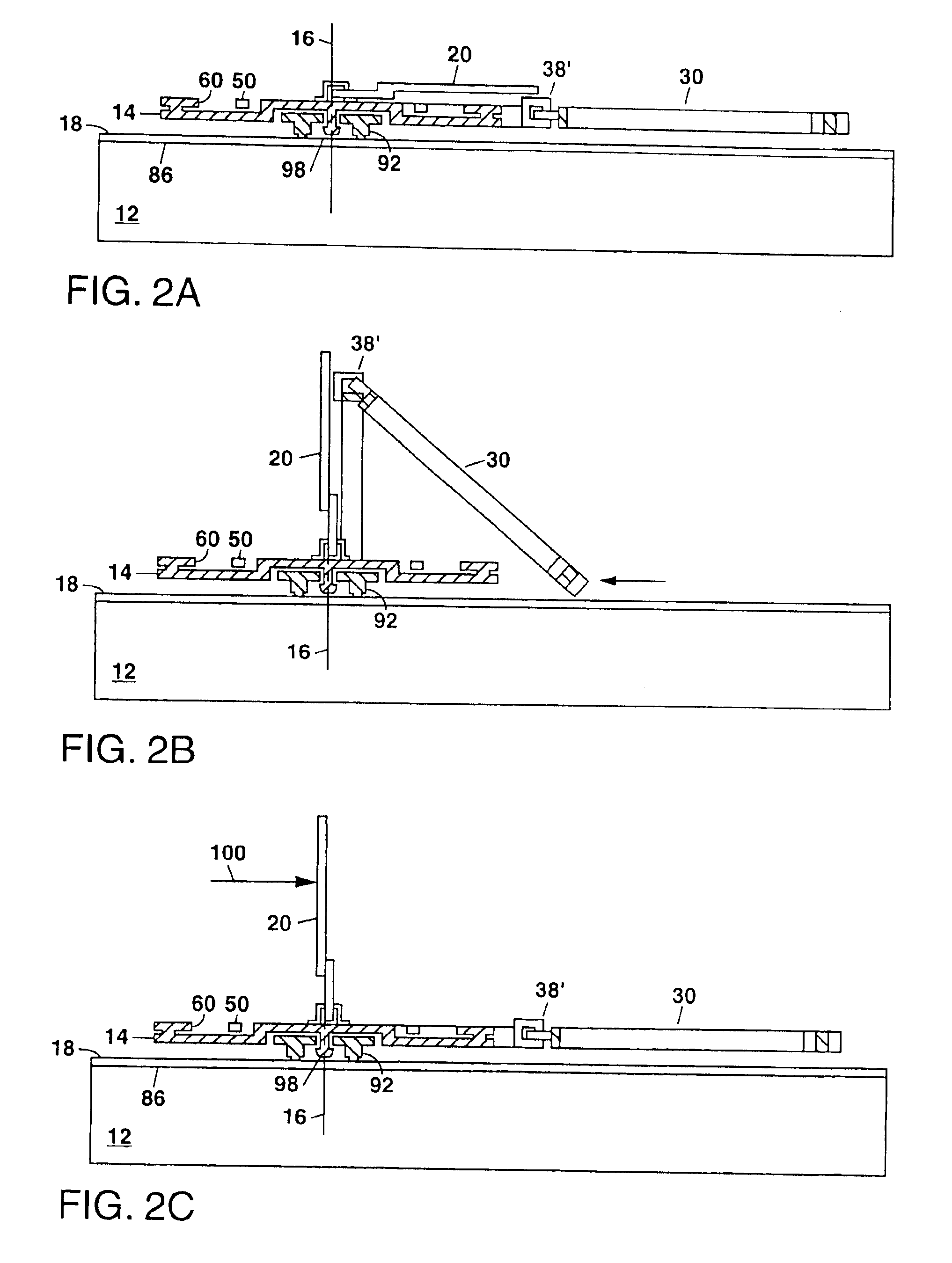
[0030]The MEM optical switching apparatus 10 in FIG. 1 further comprises a stage 14 formed on the substrate 12, with the stage 14 being rotatable about an axis 16 which is substantially perpendicular to a major surface 18 of the substrate 12 as shown in FIG. 2A, with the major surface 18 defining the plane of the substrate 12 or a layer formed thereon. An erectable mirror 20 is formed on the stage 14, with the mirror 20 being fabricated in an initial position which is substantially parallel to the major surface 18 of the substrate 12 as s...


PUM


Abstract

A microelectromechanical (MEM) optical switching apparatus is disclosed that is based on an erectable mirror which is formed on a rotatable stage using surface micromachining. An electrostatic actuator is also formed on the substrate to rotate the stage and mirror with a high angular precision. The mirror can be erected manually after fabrication of the device and used to redirect an incident light beam at an arbitrary angel and to maintain this state in the absence of any applied electrical power. A 1×N optical switch can be formed using a single rotatable mirror. In some embodiments of the present invention, a plurality of rotatable mirrors can be configured so that the stages and mirrors rotate in unison when driven by a single micromotor thereby forming a 2×2 optical switch which can be used to switch a pair of incident light beams, or as a building block to form a higher-order optical switch.

Description

GOVERNMENT RIGHTS[0001]This invention was made with Government support under Contract No. DEAC-04-94AL85000 awarded by the U.S. Department of Energy. The Government has certain rights in the invention.FIELD OF THE INVENTION[0002]The present invention relates in general to microelectromechanical devices, and in particular to microelectromechanical optical switches for redirecting an incident light beam.BACKGROUND OF THE INVENTION[0003]Optical switches can be utilized to redirect light beams in free space or between optical fibers. Many different types of optical switches fabricated by surface micromachining have been disclosed in recent years (see e.g. U.S. Pat. Nos. 5,867,302; 6,283,601; 6,366,414; 6,526,198; 6,535,318 and 6,545,385; see also L. Y. Lin et al, “Free-Space Micromachined Optical Switches for Optical Networking,”IEEE Journal of Selected Topics in Quantum Electronics, vol.5, pp. 4-9, 1999). The existing optical switches which are tiltable within a limited angular range g...

Claims


Application Information

Patent Timeline
Patent Type & Authority Patents(United States)
IPC IPC(8): G02B6/35H04Q11/00
CPCH04Q11/0005G02B6/357G02B6/3502G02B6/3518G02B6/3546H04Q2011/0052G02B6/3584H04Q2011/003
Inventor ALLEN, JAMES J.
Owner NAT TECH & ENG SOLUTIONS OF SANDIA LLC
Why Eureka
Try Eureka