Radiographic apparatus

a radiographic and apparatus technology, applied in the field of radiographic apparatus, can solve the problems of inability to achieve high-speed scans, inconvenient to operate, and insufficient to image a fast-acting internal organ such as the heart, and achieve the effect of little slippag

Inactive Publication Date: 2005-06-07
SHIMADZU CORP
View PDF2 Cites 29 Cited by
  • Summary
  • Abstract
  • Description
  • Claims
  • Application Information

AI Technical Summary

Benefits of technology

[0038]The scan device is arranged such that the main scan rotating device causes the radiation source and the detecting device to make one rotation about the sectional axis in at most 0.1 second. This enables a grasp of variations with time of a sectional image such as a dynamic sectional image of the heart, for example. By reducing the tomosynthetic angle between the sectional axis and the radiation axis linking the radiation source and the detecting device, for example, the time taken for the radiation source and the detecting device to make one rotation about the sectional axis m

Problems solved by technology

However, the apparatus disclosed in the above patent publication has the following drawback.
Since the two shafts (scan center shaft and arm shaft) are rotated as noted above, the rotation of X-ray tube 102 and image intensifier 103 about the sectional axis results in an inconvenience that resolution along the sectional axis is lower than resolution

Method used


Image

  • Radiographic apparatus
  • Radiographic apparatus
  • Radiographic apparatus

Examples


first embodiment

[0070]The following first embodiment is a solution to the problem (I).

[0071]First Embodiment

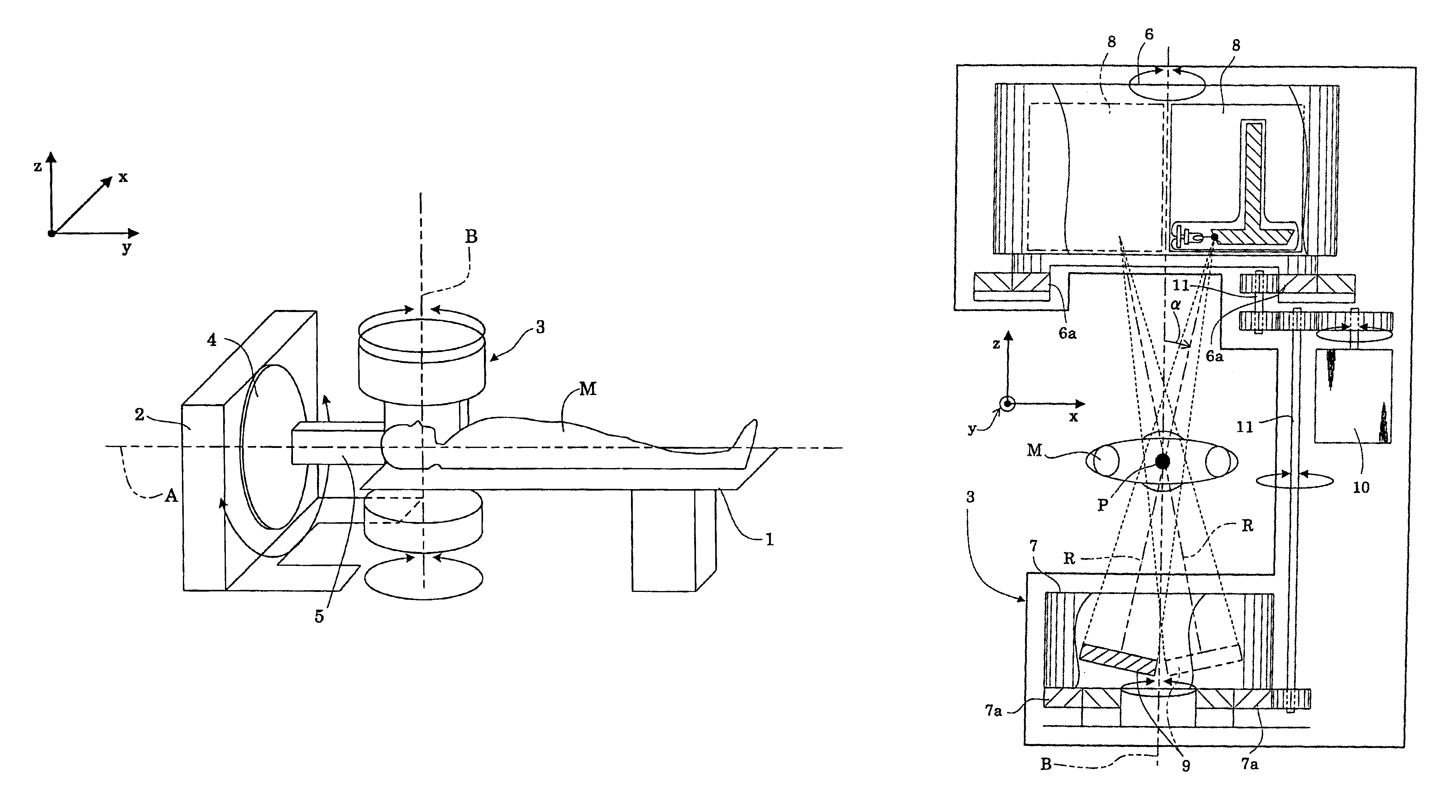
[0072]FIG. 3 is a perspective view showing an outline of a radiographic apparatus in this embodiment. FIG. 4 is a right-hand side view of an X-ray tube frame and a flat panel detector (hereinafter called “FPD” as appropriate) frame of the radiographic apparatus in this embodiment. FIG. 5 is an enlarged view of an X-ray tube in the X-ray tube frame. FIG. 6 is a block diagram of a flat panel detector (FPD) of the radiographic apparatus according to this embodiment. FIG. 7 is a perspective view of the flat panel detector (FPD) of FIG. 4 seen from an obliquely upper position, showing a relationship between gate lines and data lines forming the flat panel detector (FPD), and a sectional axis.

[0073]As shown in FIG. 3, the apparatus in this embodiment includes a top board 1 for supporting a patient M, a base 2 and a scan frame 3. The top board 1 is vertically movable and, as shown in FIG. 3, movable...

second embodiment

[0113]The following second embodiment is a solution to the problem (II).

[0114]Second Embodiment

[0115]Like reference numerals are used to identify like parts which are the same as in the first embodiment and will not be described again.

[0116]FIG. 3 is a perspective view showing an outline of a radiographic apparatus in this embodiment. FIG. 4 is a right-hand side view of an X-ray tube frame and a flat panel detector (hereinafter called “FPD” as appropriate) frame of the radiographic apparatus in this embodiment.

[0117]In this embodiment, the scanning action of X-ray tube 8 and FPD 9 by rotation about the sectional axis is defined as “main scan”, and the scanning action of X-ray tube 8 and FPD 9 by rotation about the scan center axis is defined as “auxiliary scan”. Thus, the rotary drive motor 10 for rotating the X-ray tube 8 and FPD 9 about the sectional axis corresponds to the main scan rotating device. The turntable 4 for rotating the X-ray tube 8 and FPD 9 about the scan center axi...


PUM


Abstract

The radiographic apparatus according to this invention has a scan frame with an X-ray tube frame and a flat panel type detector (FPD) frame arranged therein. The X-ray tube frame surrounds an X-ray tube, and the FPD frame surrounds an FPD. The X-ray tube frame and FPD frame are rotatable together about a sectional axis. Thus, the X-ray tube and FPD rotate on the respective frames together directly about the sectional axis (for a main scan). Further, the X-ray tube and FPD are rotatable together about a scan center axis (for an auxiliary scan). The main scan and auxiliary scan are combined to achieve a high-speed scan and improves resolution in the direction of the sectional axis, thereby obtaining a three-dimensional sectional image with isotropic spatial resolution.

Description

BACKGROUND OF THE INVENTION[0001](1) Field of the Invention[0002]This invention relates to radiographic apparatus for use in the medical field, and in industrial fields for performing non-destructive examinations, RI (Radio Isotope) examinations and optical examinations.[0003](2) Description of the Related Art[0004]A conventional apparatus of this type includes a C-shaped arm supporting an X-ray tube at one end thereof and an image intensifier at the other end. The C arm is rotatable about the body axis of a patient or object under examination, i.e. the axis of a scan center shaft. The X-ray tube and image intensifier are thus rotatable together about the patient or object to scan it and obtain sectional images thereof (as disclosed in Japanese Unexamined Patent Publication 2001-45374 (page 3 and FIG. 1), for example).[0005]However, the apparatus disclosed in the above patent publication has the following drawback. This drawback will be described with reference to FIG. 1. In FIG. 1,...

Claims


Application Information

Patent Timeline
IPC IPC(8): A61B6/03A61B6/00
CPCA61B6/04A61B6/4233A61B6/4464A61B6/4447A61B6/4441A61B6/541
Inventor OIKAWA, SHIRO
Owner SHIMADZU CORP
Why Eureka
Try Eureka