Method for operating an internal combustion engine having an injection system, injection system designed to carry out a method of this type, and internal combustion engine having an injection system of this type

Active Publication Date: 2021-12-28
ROLLS ROYCE SOLUTIONS GMBH
View PDF11 Cites 0 Cited by
  • Summary
  • Abstract
  • Description
  • Claims
  • Application Information

AI Technical Summary

Benefits of technology

The patent describes a method to detect and filter changes in the desired flow rate of a vehicle's engine, in order to prevent excessive pressure increases that can damage the engine and negatively impact its performance. The method selects the optimal time constant for filtering the setpoint flow rate based on the recorded variation in desired flow rate over time. This allows for a more dynamic response to changes in flow rate, without unnecessary high pressures that can damage the engine. The system also includes a pressure control valve that opens to its maximum width when not controlled, ensuring safe and reliable operation, even in cases of mechanical overpressure. This design prevents failures and damage to the engine and improves overall emission behavior.

Problems solved by technology

However, these high dynamics of the setpoint volumetric flow are no longer mandatory for any variation with time thereof but can rather be delayed for such events in which, for example, an excessively rapid reversal of the setpoint volumetric flow would result in an unacceptable high-pressure increase in the high-pressure storage tank.

Method used


Image

  • Method for operating an internal combustion engine having an injection system, injection system designed to carry out a method of this type, and internal combustion engine having an injection system of this type
  • Method for operating an internal combustion engine having an injection system, injection system designed to carry out a method of this type, and internal combustion engine having an injection system of this type
  • Method for operating an internal combustion engine having an injection system, injection system designed to carry out a method of this type, and internal combustion engine having an injection system of this type

Examples


Embodiment Construction

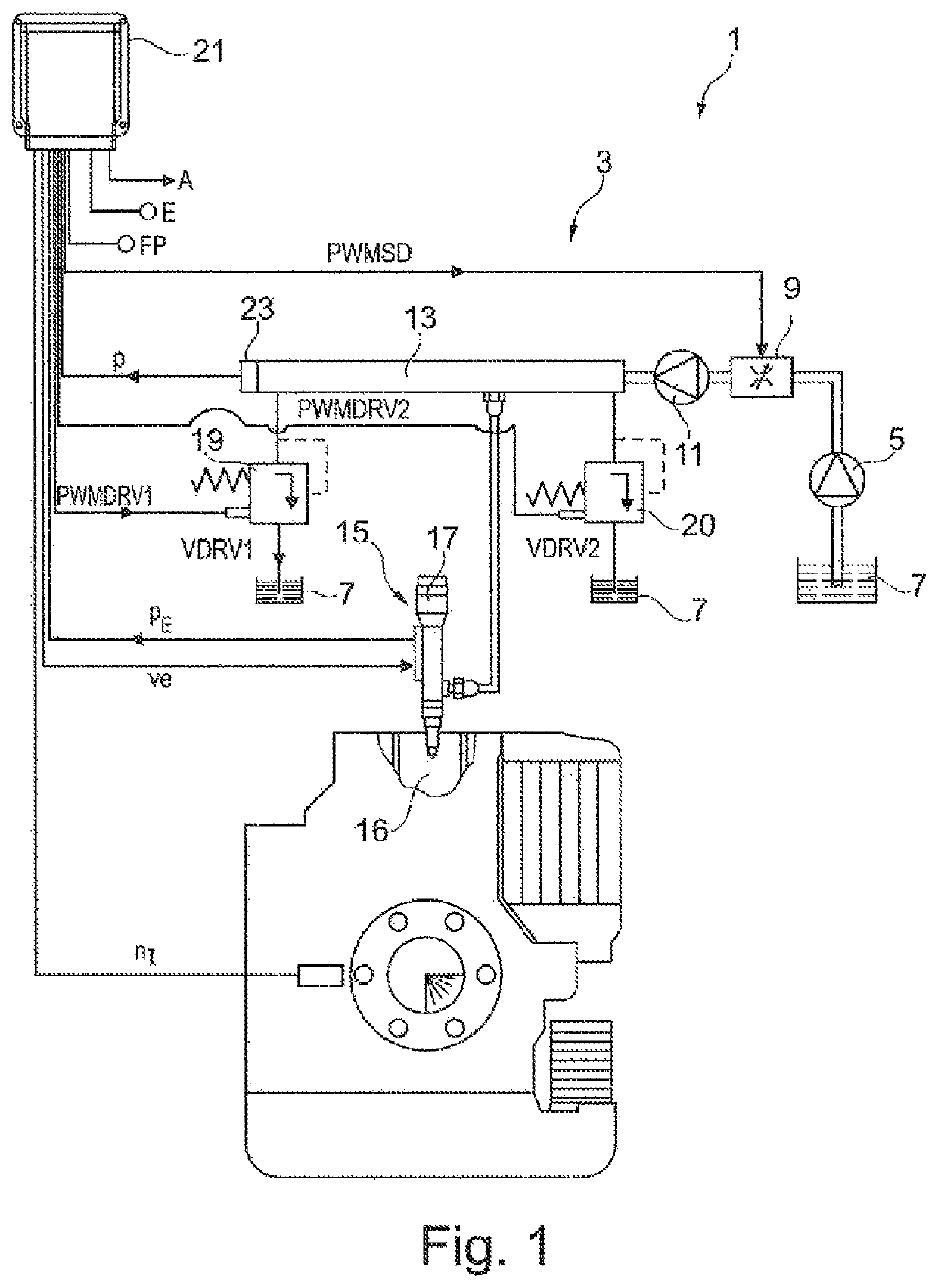
[0036]FIG. 1 shows a schematic representation of an embodiment of an internal combustion engine 1 that comprises an injection system 3. This is preferably designed as a common-rail injection system. It comprises a low-pressure pump 5 for conveying fuel from a fuel reservoir 7, an adjustable, low-pressure suction throttle 9 for influencing a volumetric fuel flow flowing through it, a high-pressure pump 11 for conveying the fuel under increased pressure into a high-pressure accumulator 13, the high-pressure accumulator 13 for storing the fuel, and a plurality of injectors 15 for injecting the fuel into combustion chambers 16 of the internal combustion engine 1. Optionally, it is possible that the injection system 3 is implemented with single accumulators, wherein then for example, a single accumulator 17 is integrated within the injector 15 as an additional buffer volume. A first, in particular electrically controllable high-pressure pressure control valve 19 is provided, via which th...


PUM


Abstract

A method for operating an internal combustion engine having an injection system which has a high-pressure accumulator, high pressure in the high-pressure accumulator being controlled via a suction throttle on the low-pressure side, acting as a first pressure control element in a first high-pressure control loop. During normal operation, a high-pressure disturbance variable is produced by a pressure regulating valve on the high-pressure side, acting as an additional pressure control element, via which fuel is re-directed from the high-pressure accumulator into a fuel reservoir, the at least one pressure regulating valve being controlled, during normal operation, based on a set volumetric flow rate for the fuel to be re-directed. A temporal development of the set volumetric rate is sensed and the set volumetric flow rate is filtered, a time constant for the filtering of the set volumetric flow rate being selected as a function of the sensed temporal development.

Description

CROSS-REFERENCE TO RELATED APPLICATIONS[0001]The present application is a 371 of International application PCT / EP2018 / 071435, filed Aug. 7, 2018, which claims priority of DE 10 2017 214 001.1, filed Aug. 10, 2017, the priority of these applications is hereby claimed and these applications are incorporated herein by reference.[0002]The invention concerns a method for operating an internal combustion engine, an injection system for an internal combustion engine set up to carry out such a method, and an internal combustion engine with such an injection system.[0003]From the German patent specification DE 10 2014 213 648 B3 a method for operating an internal combustion engine with an injection system is known, wherein the injection system comprises a high-pressure accumulator, and wherein a high pressure in the high-pressure accumulator is controlled by a low-pressure suction throttle as the first pressure control element in a first high-pressure control circuit. In a normal mode, a hig...

Claims


Application Information

Patent Timeline
IPC IPC(8): F02D41/38F02M63/02
CPCF02D41/3845F02D41/3863F02M63/025F02D2041/1422F02D2041/1432F02D41/1401F02D41/3854F02D2041/1431
Inventor DÖLKER, ARMIN
Owner ROLLS ROYCE SOLUTIONS GMBH
Why Eureka
Try Eureka