
Thermal imaging camera

a technology of thermal imaging and camera, which is applied in the field of thermal imaging cameras, can solve the problems of not primarily in the sensitivity range of the microbolometer components, but in the selection of suitable temperature ranges and a suitable display, and is not able to be meaningfully interpreted by the user, so as to reduce the amount of memory needed for buffering and processing.

Active Publication Date: 2013-01-22
DRAGER SAFETY
View PDF15 Cites 0 Cited by
  • Summary
  • Abstract
  • Description
  • Claims
  • Application Information

AI Technical Summary

Benefits of technology

The present invention is a new way to record and display thermal images. It allows two images with different dynamic ranges to be combined into one common output image while reducing noise and drift of pixel signals and the amount of memory needed for buffering and processing. This results in a more sensitive and less sensitive image being mixed in proportion to their weights, and the weighting in relation to the current output image suppresses variations in time of pixel intensity (noise). The invention also eliminates the need for separate buffering of each individual image, reducing the number of components and cost savings and improving technical facilitation. Overall, the invention offers a new type of recording and displaying thermal images that combines two images with different dynamic ranges to create a high-quality output image while minimizing the impact of noise and drift.

Problems solved by technology

When using thermal imaging cameras, the temperature differences, which are simultaneously present in a scenery to be recorded by the thermal imaging camera, are often too great to be able to be converted by the dynamic range of the electronic system (approximately linear dynamic level control range of the electronic processing chain used to record, analyze and display the thermal images) into thermal images adequately, i.e., without distortions due to saturation or noise, and they are mostly also too great to be able to be meaningfully interpreted by the user.
However, the difficulties lie not primarily in the sensitivity range of the microbolometer components, but in the selection of suitable temperature ranges and a suitable display.
This procedure has the drawback that it is highly memory-intensive and requires additional memory bandwidth.
Furthermore, the buffering delays the image sequence compared with a direct signal processing by one or more frames.
The so-called pipeline delay increases, which is extremely undesirable for real-time applications.
It is disadvantageous in both cases that a quasi-simultaneous parallel processing of the two images recorded with different sensitivities must be performed, and the combination of the image data pixel by pixel depends on arbitrarily set or empirically found correction values or threshold values, which must either be adapted continually to the current thermal scenery or preselected on the basis of certain criteria.

Method used


Image

  • Thermal imaging camera
  • Thermal imaging camera
  • Thermal imaging camera

Examples


Embodiment Construction

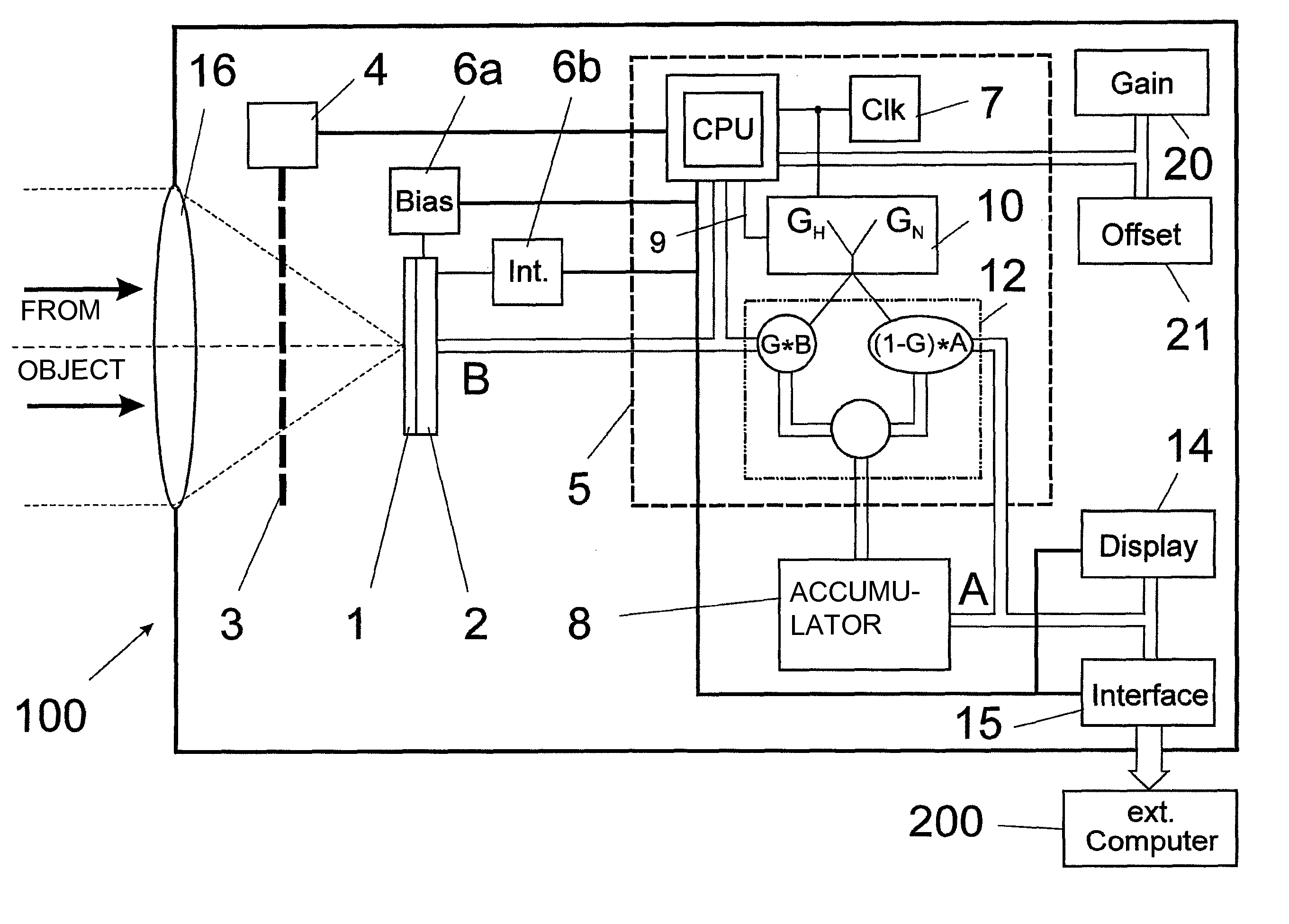
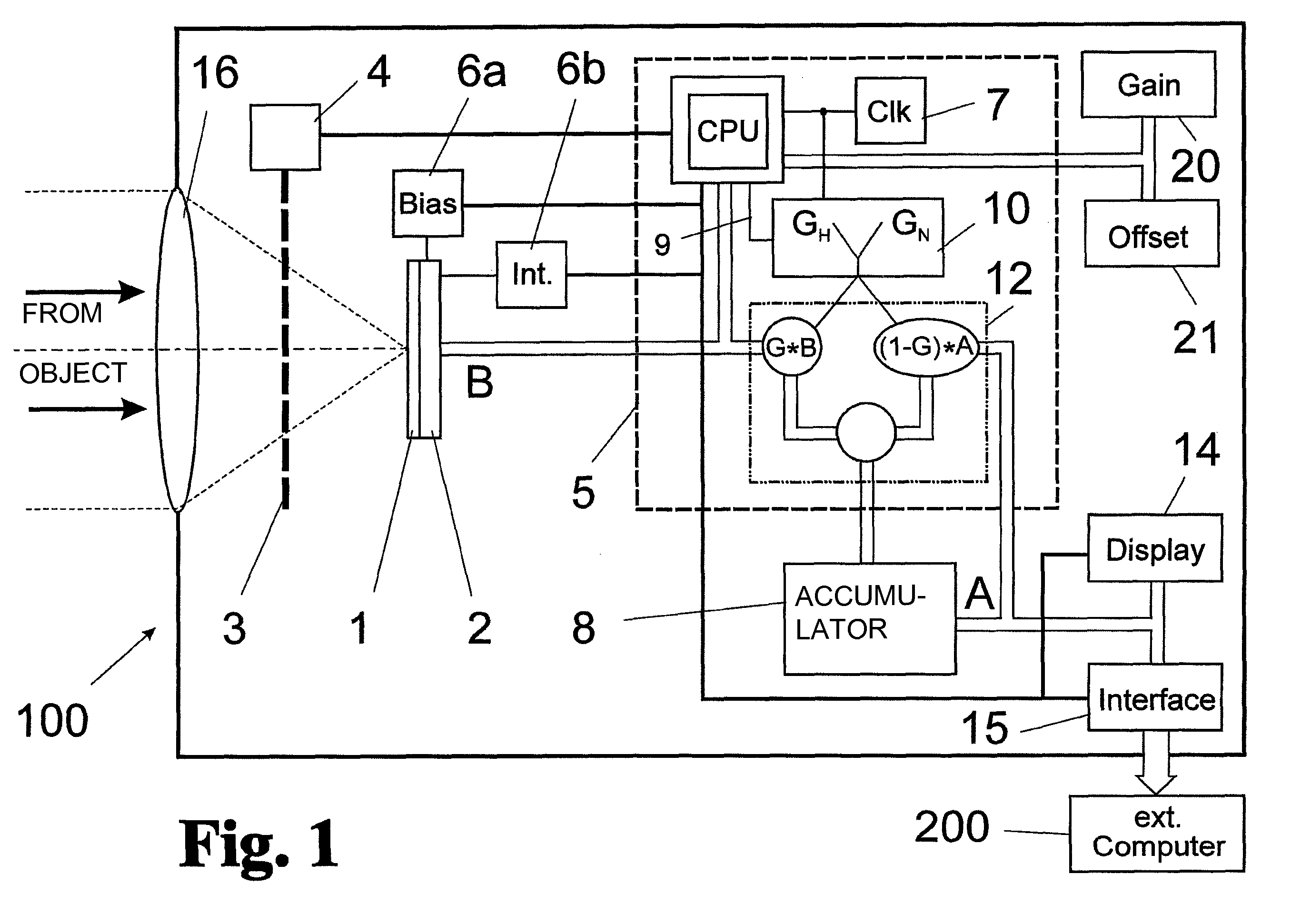
[0054]Referring to the drawings in particular, FIG. 1 shows the components of a thermal imaging camera according to one embodiment of the present invention and the networking thereof. To record a thermal image, IR radiation is imaged by means of an IR optical system 16 onto a matrix-like detector unit 1—hereinafter also called FPA (Focal Plane Array)—which is read as a complete frame in a pixel-based manner by means of the corresponding reading unit 2 and is transmitted as an original image B of the imaged thermal scene.

[0055]A processor unit 5 actuates a shutter unit called shutter 3 for opening or closing the imaging ray path by means of a shutter control 4. An original image B is produced with the shutter 3 opened.

[0056]With the shutter 3 closed, a background image of the shutter 3 is produced as a reference, which is used to compensate inhomogeneities of the microbolometer components of the FPA 1 (“non-uniformity correction” NUC, not being considered here in more detail).

[0057]P...


PUM


Abstract

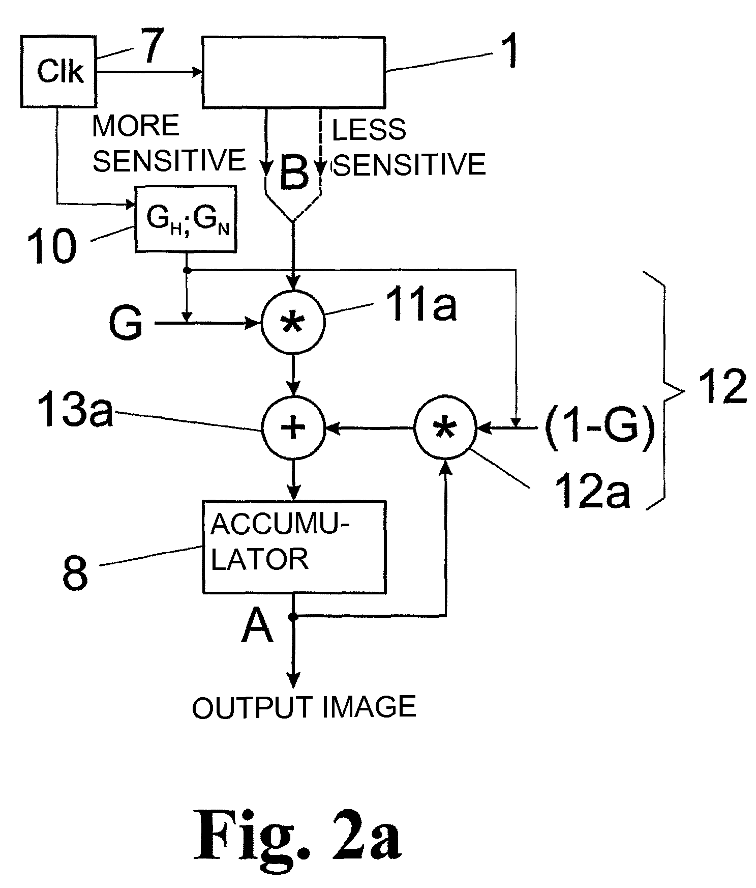
A thermal imaging camera is provided with at least two different sensitivities for alternating reading and with has a device for linking at least two more and less sensitive images read consecutively. The recording and displaying of thermal images makes it possible to combine images with two different dynamic ranges in a common thermal image, wherein the noise and drift of the pixel signals as well as the amount of storage needed for buffering and processing are reduced at the same time. An image buffering unit is designed as a common accumulator (8) for both more sensitive and less sensitive original images (B) and makes available a common output image (A). An image weighting unit (12) is arranged upstream of the accumulator (8) for weighting the more sensitive and less sensitive original images (B) read alternatingly from the detector unit (1) pixel by pixel with a settable percentage weighting function (G) and for weighting the output image (A) being buffered in the accumulator (8) pixel by pixel with a weighting function (I−G) complementary to the settable percentage weighting function as well as for the additive superimposition of the two images (B; A) for the purpose of continuously updating the output image (A).

Description

CROSS REFERENCE TO RELATED APPLICATIONS[0001]This application claims the benefit of priority under 35 U.S.C. §119 of German Patent Application DE 10 2010 023 166.5 filed Jun. 7, 2010, the entire contents of which are incorporated herein by reference.FIELD OF THE INVENTION[0002]The present invention pertains to a thermal imaging camera with a pixel-based detector unit, a processor unit and an image buffering unit, wherein the detector unit is designed with at least two different sensitivities and alternating reading of more sensitive and less sensitive images for the pixel-based recording of thermal radiation of a scene imaged onto it and the processor unit is provided for controlling the reading, preprocessing, buffering and linking of at least two consecutive more sensitive and less sensitive images read from the detector unit into a common output image.BACKGROUND OF THE INVENTION[0003]Various designs of thermal imaging cameras are offered by a number of manufacturers. A “thermal i...

Claims


Application Information

Patent Timeline
Patent Type & Authority Patents(United States)
IPC IPC(8): H01L31/00
CPCH04N5/33H04N5/35581G01J2005/0077H04N25/589H04N23/23G01J5/22H04N23/70
Inventor WEISBACH, FRANKKANEBLEI, INGOWANSING, MARKUS
Owner DRAGER SAFETY
Learn More