Telecommunication resource allocation system and method

a technology of telecommunication resource allocation and allocation system, applied in the field of telecommunication system, can solve the problems of reducing complexity, troublesome, and large number of operations along each path, so as to reduce system costs, increase overall system utilization and efficiency, and reduce the effect of application development costs

Inactive Publication Date: 2005-06-07
SECURUS TECH +1
View PDF3 Cites 36 Cited by
  • Summary
  • Abstract
  • Description
  • Claims
  • Application Information

AI Technical Summary

Benefits of technology

[0032]The telecommunication system and method of the present invention advantageously allows for allocating a telecommunication resource to an application in a dynamic manner. By keeping a single pool or multiple administrator defined pools of telecommunication resources, rather than dedicating each particular telecommunication resources to particular applications, the present invention beneficially increases overall system utilization and efficiency. Moreover, the present invention decreases system costs because more applications can be introduced into the system without having to arrange for additional dedicated telecommunication resources.
[

Problems solved by technology

Further, the complexity of conventional computer telephony products requires a large number of paths and a large number of operations along each path.
This is particularly troublesome when the computer telephony resource involves different types of hardware.
These conventional systems, however, do not reduce complexity because they can not, for example, reduce the number of paths needed to complete changes in a conventional computer telephony product.
Conventional CG developed or derived systems, however, have numerous drawbacks.
Moreover, any additional computer code input beyond that generated by the CG program is lost and must to be re-done for each change in the path to completion.
These changes, of course, are tedious and laborious and the process is prone to introducing new or additional errors into the computer telephony product.
Although these design schemes allow for having multi-vendor computer telephony resources within a single conventional c

Method used


Image

  • Telecommunication resource allocation system and method
  • Telecommunication resource allocation system and method
  • Telecommunication resource allocation system and method

Examples


second embodiment

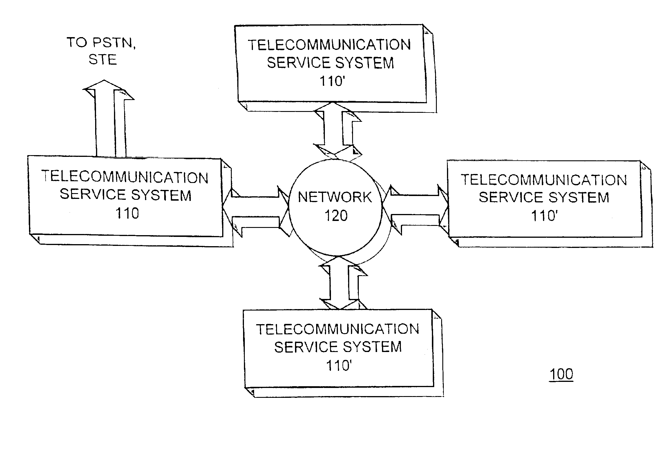
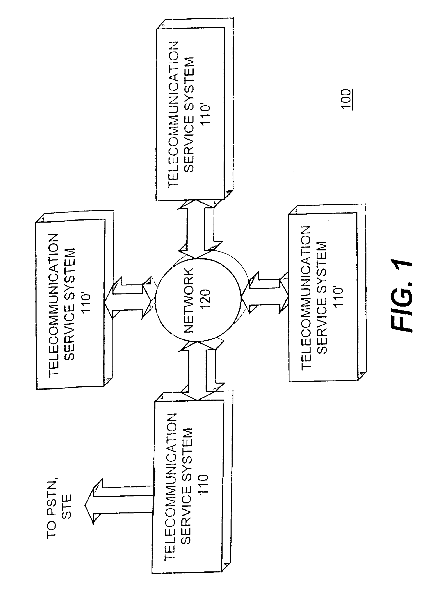
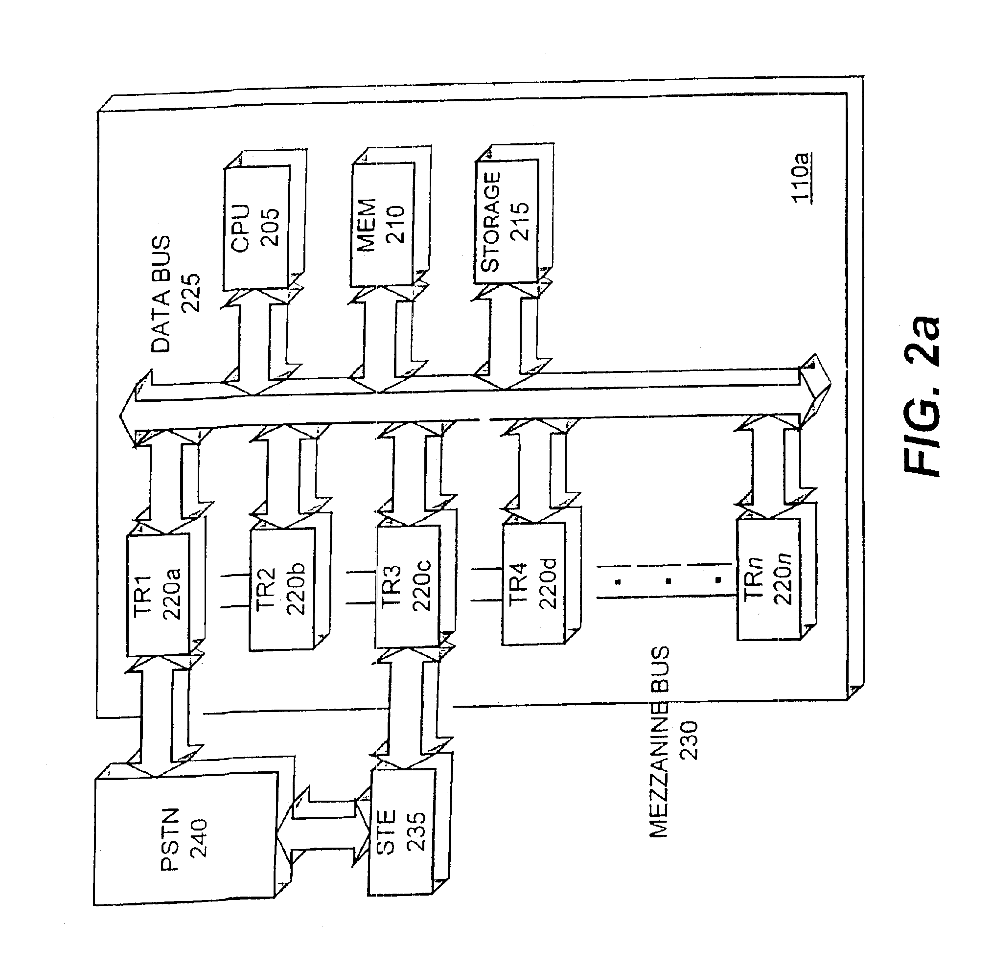
[0055]FIG. 2a is a block diagram illustrating the telecommunication service system 110a in accordance with the present invention. The telecommunication service system 110a includes a central processing unit (“CPU”) 205, a memory 210, a storage device 215, one or more telecommunication (including computer telephony) resources 220a-220n (generally 220), a data bus 225, and a mezzanine bus 230. The central processing unit 205, the memory 210, the storage device 215, and each of the telecommunication resources 220a-220n are coupled through the data bus 225. Further, each of the telecommunication resources 220a-220n are coupled to each other through the mezzanine bus 230.

[0056]The telecommunication service system 110a is coupled to one or more standard telecommunication equipment devices or systems (“STE”) 235. Specifically, each STE device 235 may be coupled to a telecommunication resource, e.g., 220c. The STE device 235 is coupled to a public switched telephone network (“PSTN”) 240.

[00...


PUM


Abstract

A telecommunication system includes telecommunication resources, points, and a connection manager. The connection manager is configured to establish connections between the telecommunications resources and the points in response to a request from an application. The connection manager uses routing tables to select the most efficient route from the available routes between a telecommunications resource and a point. The routing tables establish the connection by sending a request to allocate a telecommunications resource to a session manager.

Description

CROSS REFERENCE TO RELATED APPLICATIONS[0001]This application is a continuation of U.S. patent application Ser. No. 10 / 115,488, filed on Apr. 2, 2002, issued as U.S. Pat. No. 6,560,325 on May 6, 2003, which is a continuation of U.S. patent application Ser. No. 09 / 072,436, filed on May 4, 1998, issued as U.S. Pat. No. 6,381,321 on Apr. 30, 2002, the contents of which are herein incorporated by reference.BACKGROUND OF THE INVENTION[0002]1. Field of the Invention[0003]This invention relates to the field of telecommunications systems, and more particularly, to systems and methods for allocating telecommunication resources to an application in a telecommunications system.[0004]2. Description of the Related Art[0005]Conventional computer telephony products allow for connecting applications to particular computer telephony resources, or components. To connect these components within a computer telephony product, the application must be written to use each manufacturers programming interfac...

Claims


Application Information

Patent Timeline
IPC IPC(8): H04Q3/545H04Q3/00
CPCH04M7/0018H04Q3/0029H04Q3/0062H04Q3/54516H04Q3/66H04Q2213/13034H04Q2213/13349H04Q2213/13103H04Q2213/13109H04Q2213/13141H04Q2213/13144H04Q2213/1322H04Q2213/13299H04Q2213/13093
Inventor BROWN, BARRY D.HOGG, JR., JOHN S.
Owner SECURUS TECH
Why Eureka
Try Eureka